COMMAND RANGING & TELEMETRY UNIT CORTEX
CRT QUANTUM USER'S MANUAL
Ref. DTU 100042
Is.Rev. 5.17
Date: Dec.
03, 2021Sept. 30, 2021
This document is the property of Safran Data Systems.
It cannot be duplicated or distributed without expressed written consent.
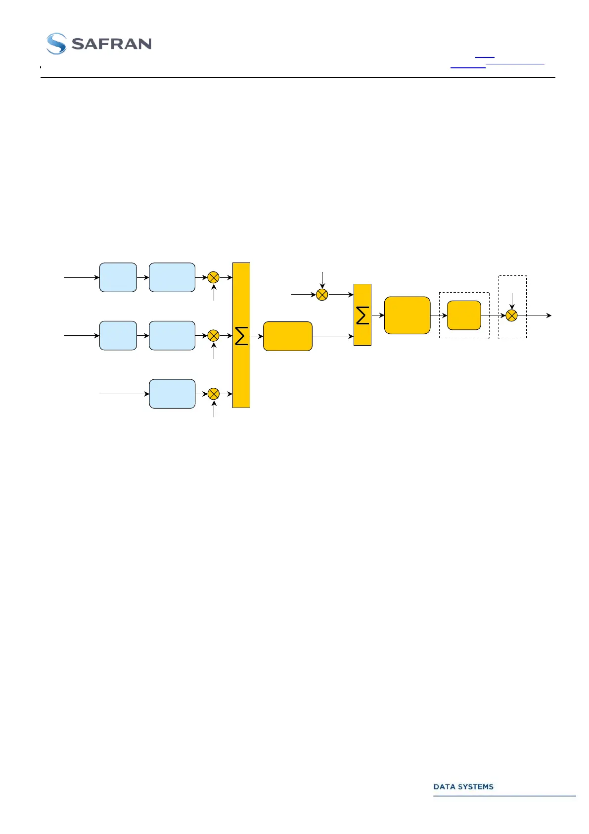
3.4.1.1. Low Bandwidth Scenario
The uplink IF carrier is modulated by any combination of low bandwidth base band signals
(TCU, TMS, RAU or external analog video input).
Signal bandwidth is limited to 125, 250 or 500 kHz (factory setting).
IF modulation is limited to PM and FM.
Sub-carrier generation can be by-passed on the TMS.
The base band video signals can be monitored if the uplink Video Test points (VIDEO 1 or
2, Sts Out/J25 to J28) are enabled (see section Annex 5).
IFM factory setting: Video only or Video + PCM.
Modulation
index
Interpolation
PM, FM
modulation
IF
filtering
(Option)
Noise
IF
outputs
PCM
encoding
TCU data
Base-band
modulation
Modulation
index
RNG sequence
Base-band
generation
(Option)
Video
Input
PCM
encoding
TMS data
Sub-carrier
modulation
Figure 51: Low Bandwidth Uplink Scenario