COMMAND RANGING & TELEMETRY UNIT CORTEX
CRT QUANTUM USER'S MANUAL
Ref. DTU 100042
Is.Rev. 5.17
Date: Dec.
03, 2021Sept. 30, 2021
This document is the property of Safran Data Systems.
It cannot be duplicated or distributed without expressed written consent.
3.8.2.1. Output Frequency
The frequency domain can be:
60 to 78 MHz for IF legacy operation. In this case, the EFC programs automatically the bypass
function
950 to 2400 MHz for L/S-Band Operation.
Important Note
Please note that,
To obtain an accurate output frequency, there are two parameters to be set:
The Output frequency of the IF Modulator (with an accuracy of the Microhertz) for the up
conversion from base band to intermediate band
The RF converter frequency (with 5MHz step*) for up conversion from intermediate band to L/S
band
The IF frequency shall be adapted accordingly to the RF frequency.
The formulas given the RF converter frequency and the IF frequency are:
EFC converter frequency = the multiple of 5MHz nearest to the RF output frequency
IF frequency = 70MHz + (RF output frequency – EFC converter frequency)
*Remark: The local oscillator used on the EFC board has been chosen to guarantee a good phase noise. In
return the frequency step of the oscillator is 5 MHz.
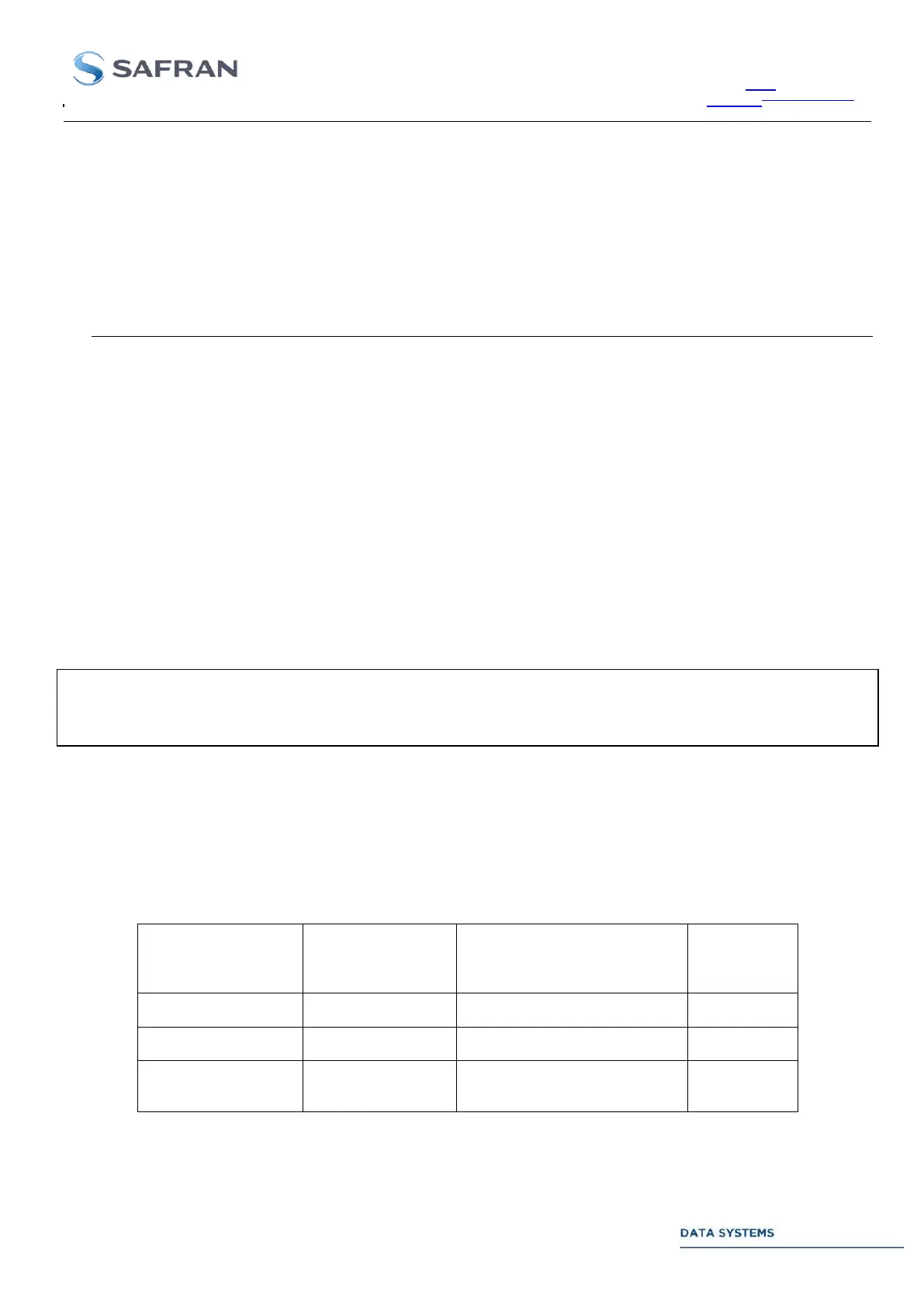
Here below some examples of uplink conversion setup:
RF output signal
frequency
70 + 2300 – 2300 = 70 MHz
70 + 1211 – 1210 = 71 MHz
70 + 952,3 – 950 = 72,3
MHz
Table 33: Examples of uplink converter setup