COMMAND RANGING & TELEMETRY UNIT CORTEX
CRT QUANTUM USER'S MANUAL
Ref. DTU 100042
Is.Rev. 5.17
Date: Dec. 03, 2021Sept.
30, 2021
This document is the property of Safran Data Systems.
It cannot be duplicated or distributed without expressed written consent.
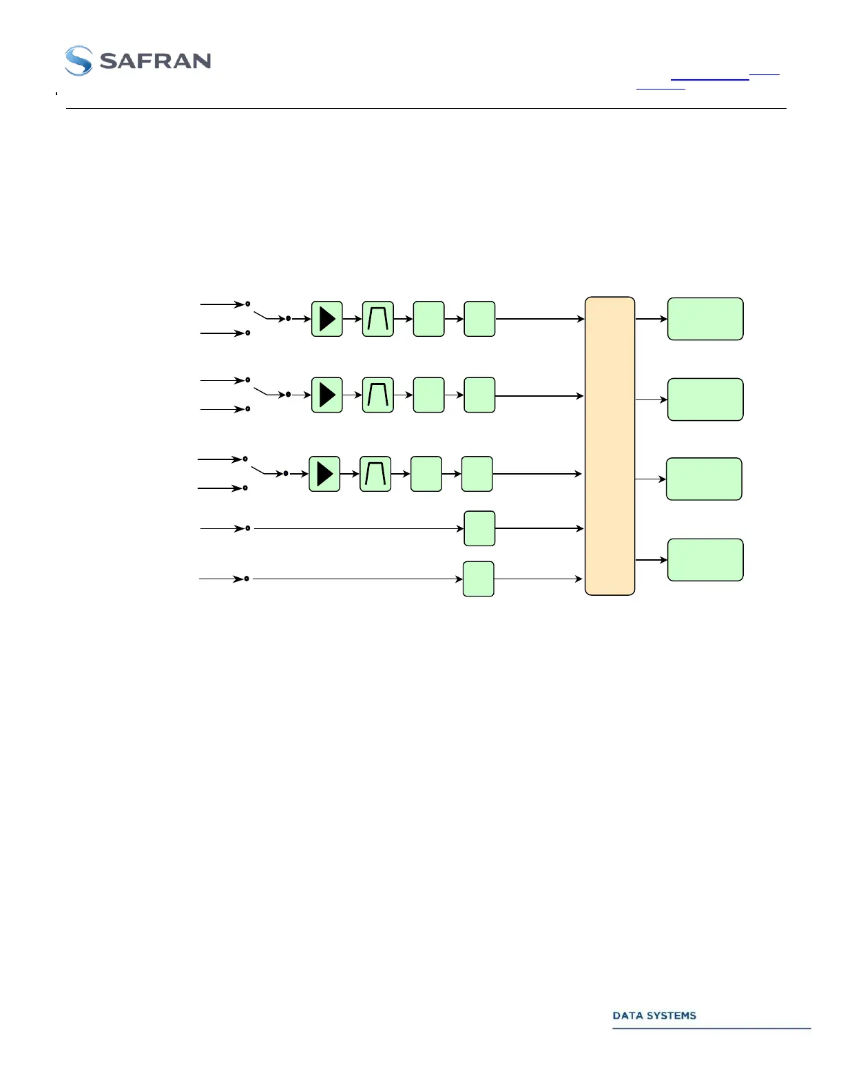
1.4.2.2.2. Downlink Input Signal Selection
Up to four IF carriers can be simultaneously demodulated (IF Receivers 1, 2, 3 & 4) with limitations (data rate,
bandwidth ...) that are described in Section 3. Selection of the IF or Auxiliary signals is by analog or digital
switches as shown in next figure:
AGC A/D
AGC A/D
A/D
5 x 4
DIGITAL
MATRIX
IF RECEIVER # 1
IF RECEIVER # 2
IF RECEIVER # 4
NOMINAL
ALTERNATE
IF STAGE # 1
IF STAGE # 2
NOMINAL
ALTERNATE
AUXILIARY 1
IF RECEIVER # 3
A/D
AUXILIARY 2
AGC A/D
NOMINAL
ALTERNATE
IF STAGE # 3
Figure 5: Downlink Input Signal Selection
On the MSP board, each IF Receiver can be separately programmed to receive: IF-1 or IF-2 or IF-3 or Auxiliary-1
or Auxiliary-2.
Each analog switch on the Main Signal Processing board (IF # 1, IF # 2 and IF # 3) allows to select a NOMINAL
or ALTERNATE IF signal.
AUXILIARY input stages have limited hardware (no amplification, no filtering, no AGC). They only allow to
receive noise-free signals with low amplitude variations (typically: test loops at baseband or IF, Telecommand
data demodulation, etc...).