COMMAND RANGING & TELEMETRY UNIT CORTEX
CRT QUANTUM USER'S MANUAL
Ref. DTU 100042
Is.Rev. 5.17
Date: Dec.
03, 2021Sept. 30, 2021
This document is the property of Safran Data Systems.
It cannot be duplicated or distributed without expressed written consent.
3.3.5.2. Outputs
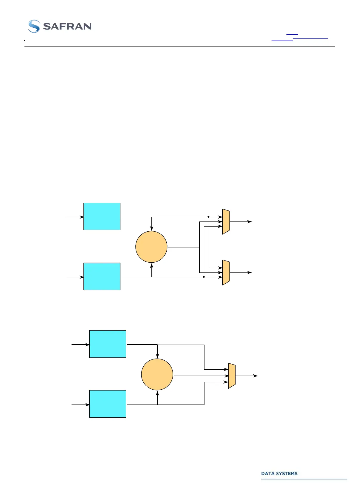
3.3.5.2.1. Post Detection Diversity Combining
In Video Mode: the DCU has two separate outputs. Output # 1 can be routed to a low bandwidth
telemetry unit (TMU) while Output # 2 can feed either a low bandwidth telemetry unit or a high bandwidth
telemetry unit with sub-carrier. Each DCU output can be separately programmed to Channel A or Channel
B or Best Channel or Combined Channels.
In PCM Mode: the DCU offers a single output (Output# 1) connected to a high bandwidth, direct PCM
telemetry unit.
Note: a status in the DCU monitoring table indicates which IF Receiver is Channel A and which one is Channel
B.
Next figure illustrates the signal paths through the combining system:
Channel A
IF Demodulation
Channel B
IF Demodulation
Combiner
PM demodulation
Polarization 1
Polarization 2
POST DETECTION DIVERSITY COMBINING IN VIDEO MODE :
A
B
To :
Telemetry Units (Low BW only)
Ranging Unit
Video test outputs
mA + nB
(m + n = 100%)
Output 1
Output 2
To :
Telemetry Units
Video test outputs
Channel A
IF Demodulation
Bit Synchronization
BP, DM-M/S decoding
Channel B
IF Demodulation
Bit Synchronization
BP, DM-M/S decoding
Combiner
PCM/BPSK,
PCM/QPSK,
PCM/OQPSK
or PCM/PM
Polarization 1
Polarization 2
POST DETECTION DIVERSITY COMBINING IN PCM MODE :
A
B
To :
Viterbi decoder
differential decoder
test points
Frame Synchronizer
Output 1
mA + nB
(m + n = 100%)
Figure 28 : Post detection Diversity Combining outputs