COMMAND RANGING & TELEMETRY UNIT CORTEX
CRT QUANTUM USER'S MANUAL
Ref. DTU 100042
Is.Rev. 5.17
Date: Dec.
03, 2021Sept. 30, 2021
This document is the property of Safran Data Systems.
It cannot be duplicated or distributed without expressed written consent.
3.4.1.2. High Bandwidth Scenario
The IF carrier is modulated by a video or/and PCM signal.
In case of single high bandwidth PCM signal, all modulation schemes are supported:
PCM/PM, PCM/FM, BPSK, QPSK, OQPSK modulation, with filtering capability (matched
filters).
Sub-carrier generation can be by-passed.
Signal bandwidth: ≤ 2 MHz if the sub-carrier is enabled or up to 40 Mbps for direct PCM
modulation (modulation dependent).
TCU or TMS monitoring (data + clock) on output test points if one data I/O test set is
enabled (see section 2.3.4.2 and Annex 5).
External data & clock input on test points if one data I/O test set is enabled (see section
2.3.4.2 and Annex 5).
IFM factory setting: PCM only or Video + PCM or PCM + PCM). Sub-carriers are not
allowed in PCM and PCM + PCM modes.
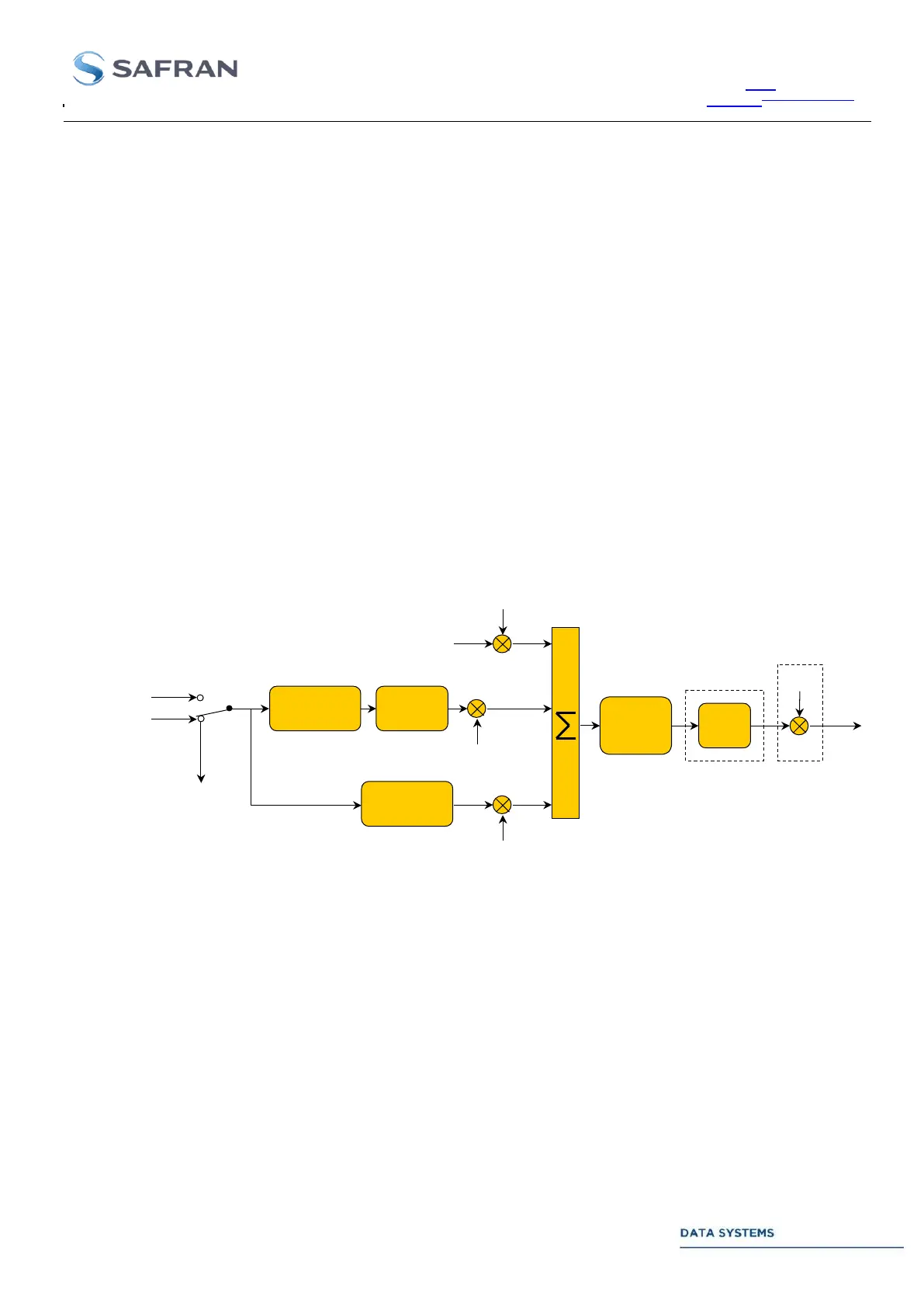
3.4.1.2.1. PM and FM Modulation
3.4.1.2.1.1. Single PCM Input Signal
Modulation
index
PM, FM
modulation
IF
filtering
(Option)
Noise
IF
outputs
(Option)
Video
Input
Sub-carrier
modulation
Modulation
index
Modulation
index
PCM
& convolutional
encoding
Built-in TMS or TCU
External data + clock
Data & clock
monitoring
PCM
& convolutional
encoding
Figure 52: High Bandwidth Uplink Scenario with PCM Input Signal (PM, FM)