EasyManua.ls Logo

Safran CORTEX CRT Quantum - Figure 20: DA-15 Female Connector, Front View; Table 16: Interconnection Panel

Safran CORTEX CRT Quantum
346 pages
Print Icon
To Next Page IconTo Next Page
To Previous Page IconTo Previous Page
Loading...
COMMAND RANGING & TELEMETRY UNIT CORTEX
CRT QUANTUM USER'S MANUAL
Ref. DTU 100042
Is.Rev. 5.17
Date: Dec.
03, 2021Sept. 30, 2021
© Safran Data Systems
This document is the property of Safran Data Systems.
It cannot be duplicated or distributed without expressed written consent.
Page 16
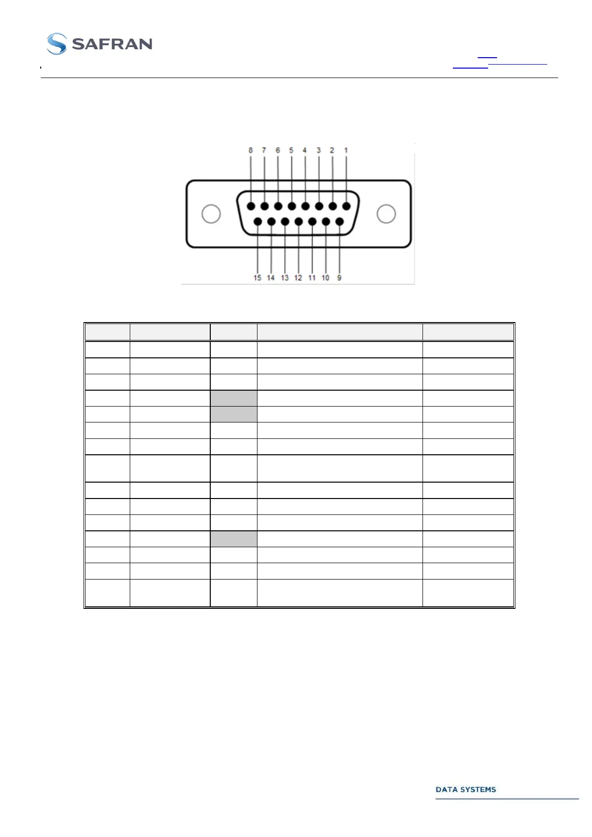
For applications requiring RS422 Differential signal interfacing, SET #3 and SET #4 can be used. The picture
and table below describes the pin assignment of the RS422 connector.
Figure 20: DA-15 Female connector, front view
Pin #
Signal name
In/Out
Signal description
Electrical
1
I_IN_POS
IN
I Data Input, positive
RS-422
2
Q_IN_POS
IN
Q Data Input, positive
RS-422
3
CLK_IN_POS
IN
Clock Input, positive
RS-422
4
GND
Ground
Ground
5
GND
Ground
Ground
6
I_OUT_NEG
OUT
I Data Output, negative
RS-422
7
Q_OUT_NEG
OUT
Q Data Output, negative
RS-422
8
CLK_OUT_N
EG
OUT
Clock Output, negative
RS-422
9
I_IN_NEG
IN
I Data Input, negative
RS-422
10
Q_IN_NEG
IN
Q Data Input, negative
RS-422
11
CLK_IN_NEG
IN
Clock Input, negative
RS-422
12
GND
Ground
Ground
13
I_OUT_POS
OUT
I Data Output, positive
RS-422
14
Q_OUT_POS
OUT
Q Data Output, positive
RS-422
15
CLK_OUT_P
OS
OUT
Clock Output, positive
RS-422
Table 16: Interconnection Panel. RS422 Data I/Os

Table of Contents