COMMAND RANGING & TELEMETRY UNIT CORTEX
CRT QUANTUM USER'S MANUAL
Ref. DTU 100042
Is.Rev. 5.17
Date: Dec.
03, 2021Sept. 30, 2021
This document is the property of Safran Data Systems.
It cannot be duplicated or distributed without expressed written consent.
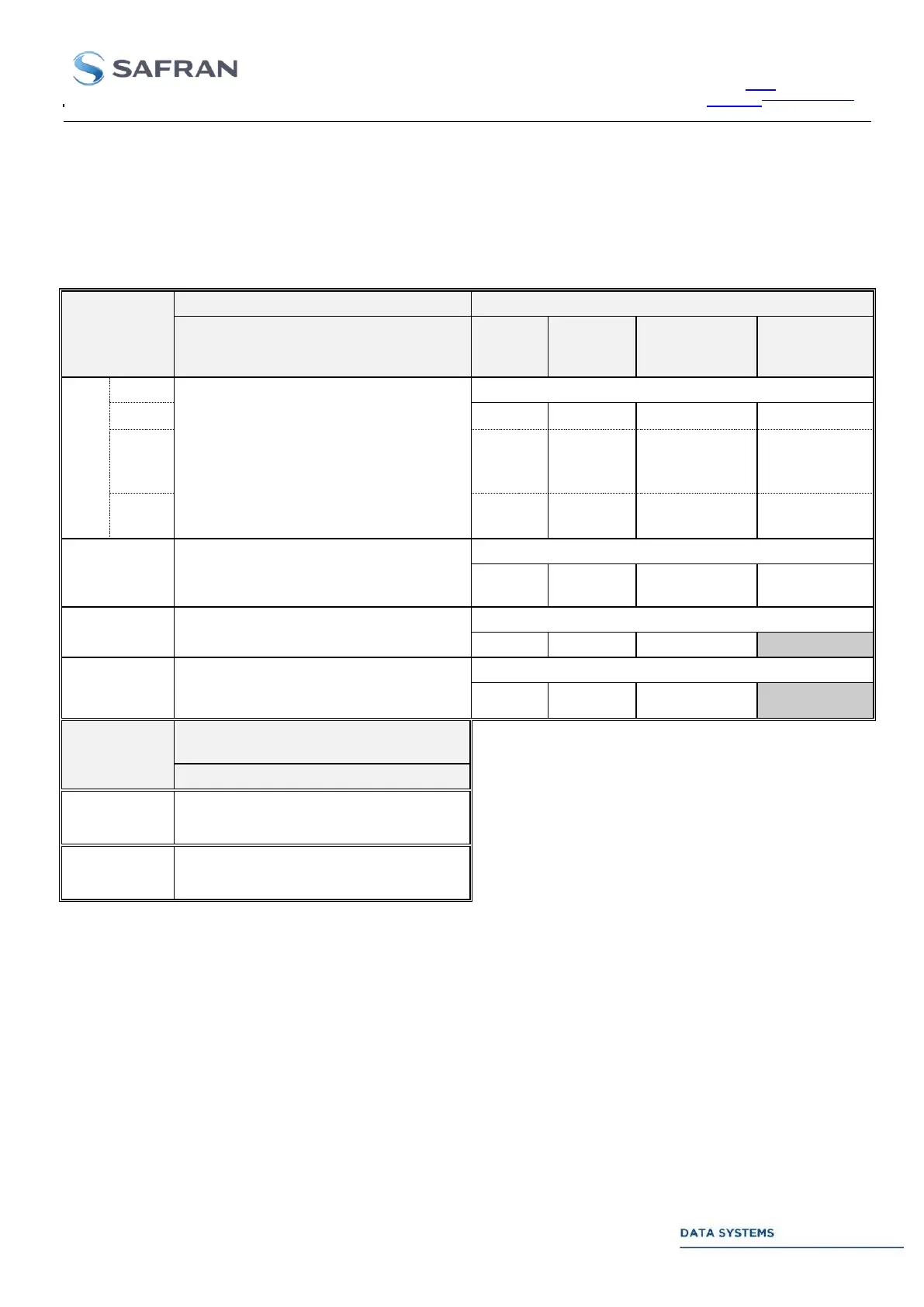
2.3.4.1. Video Test Points
The Video test points are fully programmable from the « CONFIG » window (refer to the MCS User’s Manual and
the TCP/IP Interface Specification, Global Table) for monitoring any baseband signal:
Analog test points (uplink signals)
TCU : analog output
(FSK, PSK, Execute tone, …)
TCU output : data, clock & transmit status
I data after
PCM
encoding
Q data after
PCM
encoding
RAU : analog output
(range tones or modulated S/C)
RAU output : tone rank & tone ID
TMS : analog output (PCM/BPSK)
TMS output : data & clock (if PSK modulation ON)
IFM : analog input
(for TCU or TMS modulating signal
only)
IFM input : data & clock of modulating signal
Analog test points (downlink
signals)
IFR : analog demodulated output
DCU : combiner analog demodulated
output (as selected for Output 1)
Table 14: Interconnection Panel. Uplink Video Test Points
Note 1: Active (5 V) during FSK or PSK modulation or transmission of an Execute or pseudo-earth pulse.
Note 2: Set to 5 V at the beginning of the ranging sequence (transmission of first tone). Drops to 0 V at:
The first measurement performed on the first tone (INMARSAT and LMCO standards) or
The first measurement on the major tone (ESA, ESA-like, USB, and ESA code standard).