COMMAND RANGING & TELEMETRY UNIT CORTEX
CRT QUANTUM USER'S MANUAL
Ref. DTU 100042
Is.Rev. 5.17
Date: Dec.
03, 2021Sept. 30, 2021
This document is the property of Safran Data Systems.
It cannot be duplicated or distributed without expressed written consent.
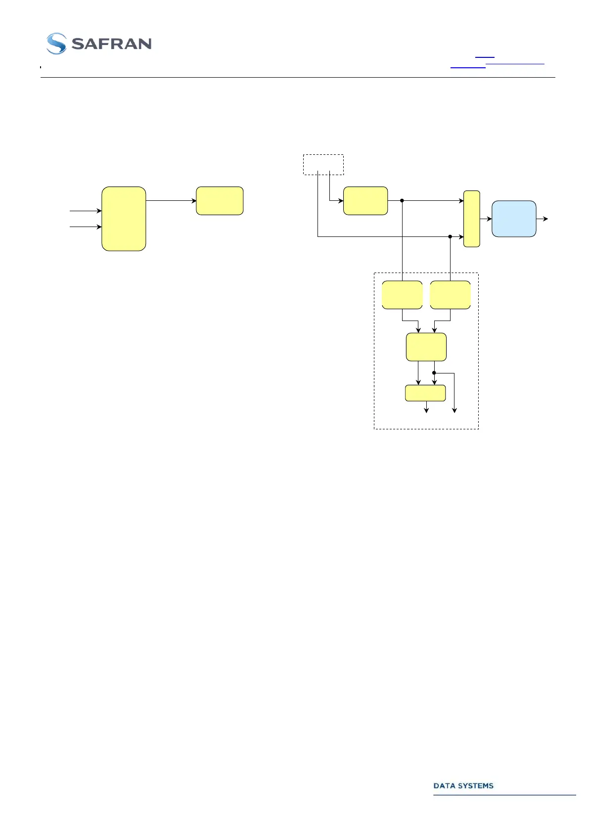
c- External Input to Viterbi Decoder (TMU table/offset 26 = 2. GUI: Frame Sync. Input = Ext. Vit.
1):
Differential
decoder
interleaving
Frame
Synchronizer
Interleaving
Differential
encoder
Invert/
swap
Differential
encoder
I out Q out
PCM/PM,
BPSK,
QPSK,
OQPSK
demodulator
& B/S
IF inputs
Aux. inputs
BP, DM-M
decoder
(Option)
Q in I in
(Option)
I
Figure 39: M Chain : I/O Ports (HBW direct PCM)
Data routing for BPSK and PCM/PM demodulation is on I channel.
Phase and channel ambiguity solving is by the Frame Synchronizer if differential encoding is not
used. In BPSK and PCM/PM mode, phase ambiguity solving is by the differential decoder (if
differential encoding is used).
Test points and external input to the Frame Synchronizer or Viterbi Decoder are available if one of
the downlink data I/Os Test Sets is enabled. See section 2.3.4.2, Annex 5 and TMU monitoring
table, status offset 26 for more details.
Auxiliary inputs: restricted to noise & spurious-free signal with limited amplitude variations.
Direct input to the Bit Synchronizer: Not available.