COMMAND RANGING & TELEMETRY UNIT CORTEX
CRT QUANTUM USER'S MANUAL
Ref. DTU 100042
Is.Rev. 5.17
Date: Dec.
03, 2021Sept. 30, 2021
This document is the property of Safran Data Systems.
It cannot be duplicated or distributed without expressed written consent.
c- External Input to Viterbi Decoder (TMU table/offset 26 = 2. GUI: Frame Sync. Input = Ext. Vit.
1) :
PCM/PM,
BPSK,
QPSK,
OQPSK
demodulator
& B/S
IF inputs
Aux. inputs
BP, DM-M
decoder
Viterbi
decoder
differential
decoder
Frame
Synchronizer
differential
encoder
invert/
swap
I out
(Option)
(Option)
Q in I in
(Option)
I rail
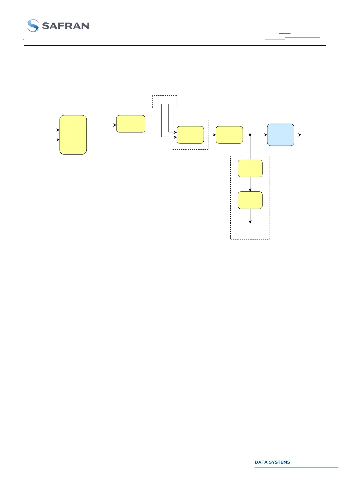
Figure 40: TM Chain : I/O Ports (HBW direct PCM with Single Viterbi)
Data routing for BPSK and PCM/PM demodulation is on I channel.
Phase ambiguity solving is by the differential decoder. In QPSK, OQPSK and SOQPSK
mode, channel ambiguity solving is by the single dual-input Viterbi decoder.
Test points and external input to the Frame Synchronizer or Viterbi Decoder are available if
one of the downlink data I/Os Test Sets is enabled. See section 2.3.4.2, Annex 5 and TMU
monitoring table, status offset 26 for more details.
Hard decision applies to external input to the Viterbi decoder (scenario c).
Auxiliary inputs: restricted to noise & spurious-free signal with limited amplitude variations.
Direct input to the Bit Synchronizer: Not available.