COMMAND RANGING & TELEMETRY UNIT CORTEX
CRT QUANTUM USER'S MANUAL
Ref. DTU 100042
Is.Rev. 5.17
Date: Dec. 03, 2021Sept.
30, 2021
This document is the property of Safran Data Systems.
It cannot be duplicated or distributed without expressed written consent.
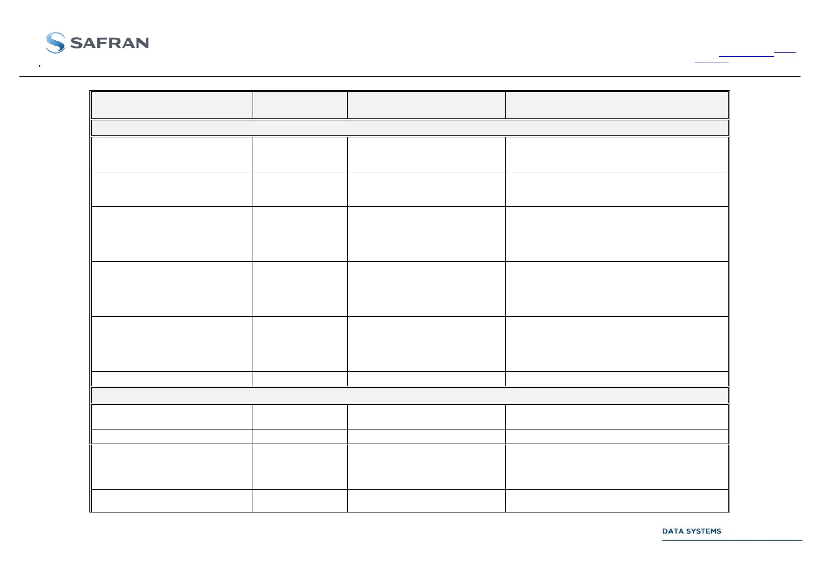
Electrical characteristics
Uplink video test signals
(see section 2.3.4.1 for assignment to
internal signals)
DC to 25 MHz (-3 dB attenuation)
2Vpp (adjustable, see note 1)
50 Ω
Uplink video test signals
(see section 2.3.4.1 for assignment to
internal signals)
DC to 25 MHz (-3 dB attenuation)
2Vpp (adjustable, see note 1)
50 Ω
AGC voltage Output 1
Non coherent AGC :
significant from -20 dBm to –60 dBm,
Coherent IF level :
significant from 0 dBm to –100 dBm)
0 to 10 V, 10 dB/V
+ 2 V = -20 dBm,
+10 V = -100 dBm
Requires high impedance input
AGC voltage Output 2
Non coherent AGC :
significant from -20 dBm to –60 dBm,
Coherent IF level :
significant from 0 dBm to –100 dBm)
0 to 10 V, 10 dB/V
+ 2 V = -20 dBm,
+10 V = -100 dBm
Requires high impedance input
AGC voltage Output 3
Non coherent AGC :
significant from -20 dBm to –60 dBm,
Coherent IF level :
significant from 0 dBm to –100 dBm)
0 to 10 V, 10 dB/V
+ 2 V = -20 dBm,
+10 V = -100 dBm
Requires high impedance input
Reference time code input
(IRIG-B122)
Reference 1-PPS clock input
Reference clock input # 1
5, 10 or 100 MHz
0.2 to 5 Vpp
DC 4 V
50 Ω
Reference clock input # 2
5, 10 or 100 MHz
0.2 to 5 Vpp