Saia-Burgess Controls AG
Manual I/O-modules for PCD1 │ PCD2 series │ Document 27-600 – Release ENG09 │ 2019-05-01
5-91
I/O modules PCD1|PCD2
PCD2.W6x5
5
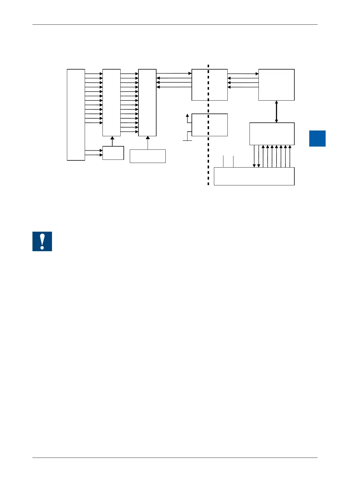
Block diagram
A0
COM
A1
COM
A2
COM
A3
COM
A4
COM
A5
COM
DAC
Reference
Voltage 2.5 V
Galvanically
separated
interface
Electrical isolation
VCC
COM
+5 V GND
Filter
+Uin
-Uin
Programming
Classic: For programming the modules, an FBox is available.
xx7andRIOs:thermwarereadsinthevaluesaccordingtotheconguration(I/O
Builderornetworkcongurator)
Watchdog:Thismodulecanbeusedonallbaseaddresses;thereisnointeraction
with the watchdog on the CPUs. For details, please refer to the section A4
“Hardware Watchdog”, which describes the correct use of the watchdog in
conjunction with PCD components.