Saia-Burgess Controls AG
Manual I/O-modules for PCD1 │ PCD2 series │ Document 27-600 – Release ENG09 │ 2019-05-01
5-90
I/O modules PCD1|PCD2
PCD2.W6x5
5
IntheFBstheoutputvaluesarenotlimitedto0 … 1023,sothewholerangeofthe
module can be used.
For voltages > 10 V or currents > 20 mA, values >1023 may be output, and for
voltages < 0 V or
< –10 V, negative values may be output. (With the W615 it is not possible to out-
put negative currents).
This extended range does depend on the tolerances of the components, and can-
not be guaranteed.
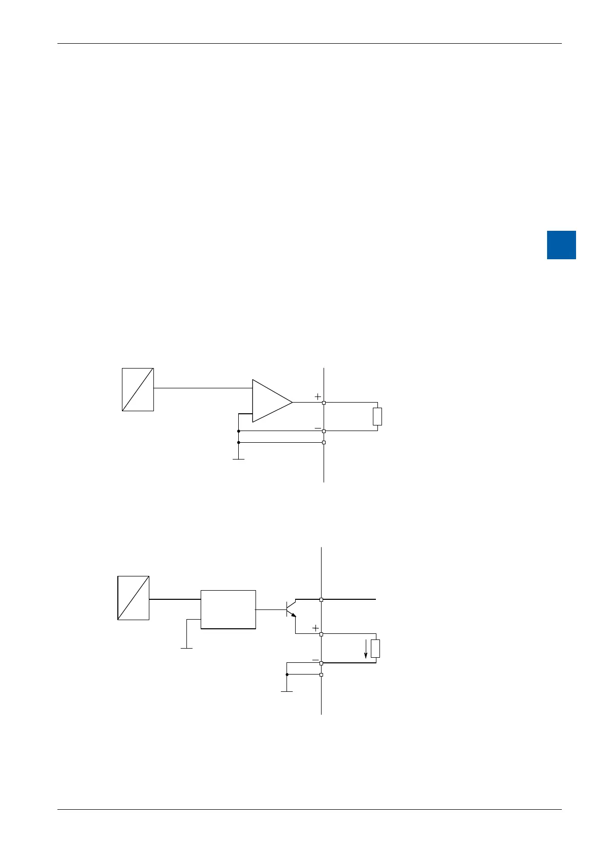
Connection concept for voltage and current outputs
The voltage and current output signals are connected directly to the 14-pole termi-
nalblock(A0 … A5/A3and-).
The following connection diagram shows a typical wiring layout for:
● voltageoutputswiththePCD2.W605and.W625modulesor
● currentoutputsforthePCD2.W615module
Connection for 0 … 10 V (W605) or –10 V … +10 V (W625):
D
A
5
U
13
4
(A2)
For voltage outputs no external supply is needed.
Connection for 0 … 20 mA (W615)
4 (A2)
D
A
5
I
VOLTAGE
CONTROLLED
CURRENT
SOURCE
13
12
An external 24 VDC supply is required for current outputs.