Saia-Burgess Controls AG
Manual I/O-modules for PCD1 │ PCD2 series │ Document 27-600 – Release ENG09 │ 2019-05-01
5-89
I/O modules PCD1|PCD2
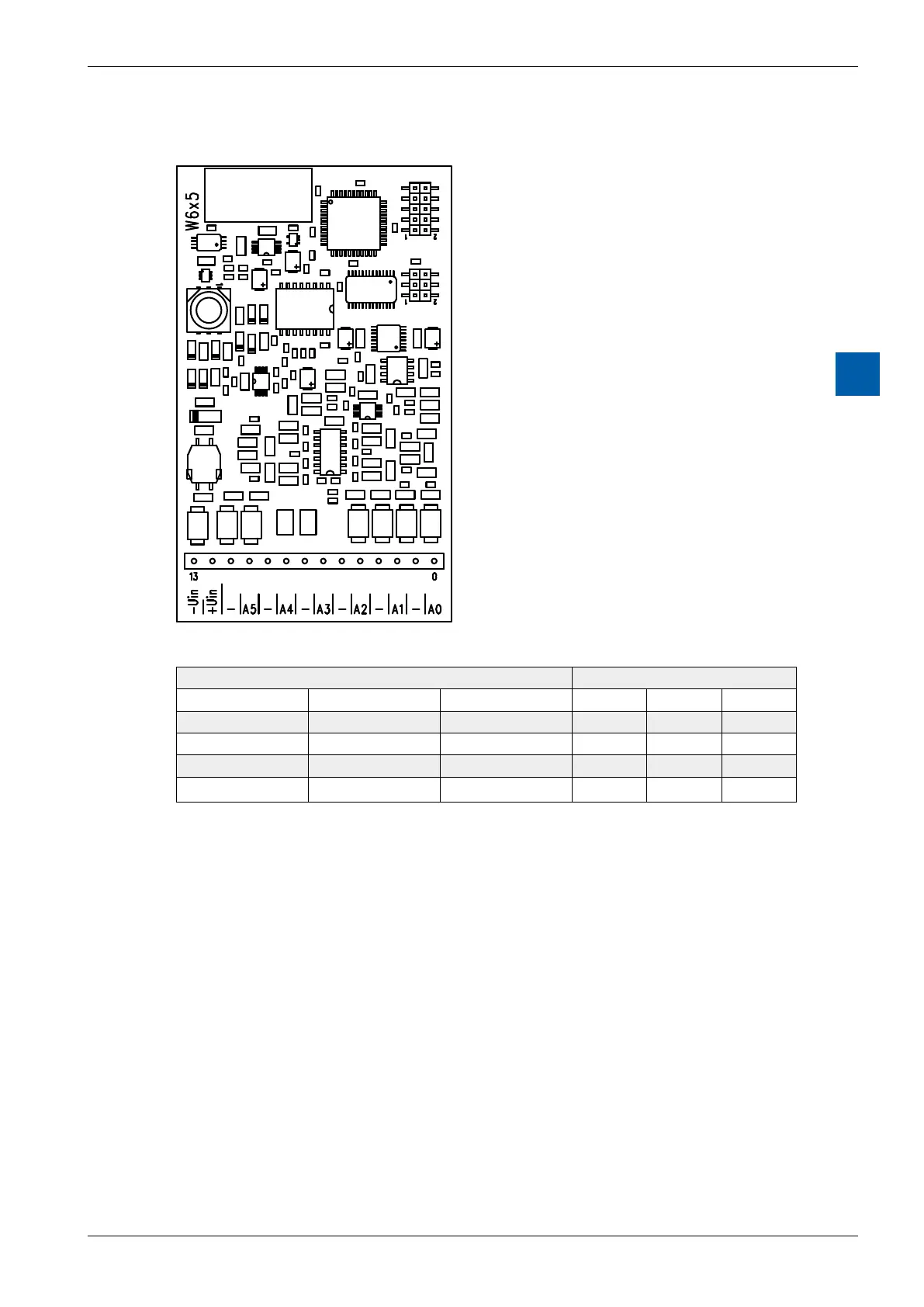
PCD2.W6x5
5
Terminals
Digital/analogue values
Output signals and type Digital values
PCD2.W605 PCD2.W615 PCD2.W625 Classic xx7 Simatic
+ 10.0 V + 20 mA +10 V 1023 1023 27684
+ 5.0 V + 10 mA 0 V 512 512 13842
+ 4 mA 205 205 5530
0 V 0 mA –10 V 0 0 0
Notes on the output range
BalancingtheosetandtheamplicationisdoneforthePCD2.W6x5digitallyby
the µC. As there is no potentiometer, the output range has been slightly enlarged
to cover maximum values even in the worst case.
Typical output range (without component tolerances):
PCD2.W605: – 0.26V … +10.36V(insteadof0 … +10V)
PCD2.W615: 0mA … 21.4mA(insteadof0 … 20mA)
PCD2.W625: – 10.62V … 10.36V(insteadof– 10 … +10V)
This range is broken down on a 10 bit scale (1024 steps), as before. The result is
the following LSB resolution:
PCD2.W605: 1 LSB = 10.38 µV
PCD2.W615: 1 LSB = 21.7 µA
PCD2.W625: 1 LSB = 20.75 µV
Withthisbalancethenominalrange(0 … 10V)isnowscaled0 … 1023,makingit
possible for the output value not to change on an increase of 1 LSB.