Saia-Burgess Controls AG
Manual I/O-modules for PCD1 │ PCD2 series │ Document 27-600 – Release ENG09 │ 2019-05-01
5-103
I/O modules PCD1|PCD2
PCD2.W525 Combined analogue input/output module with galvanic isolation
5
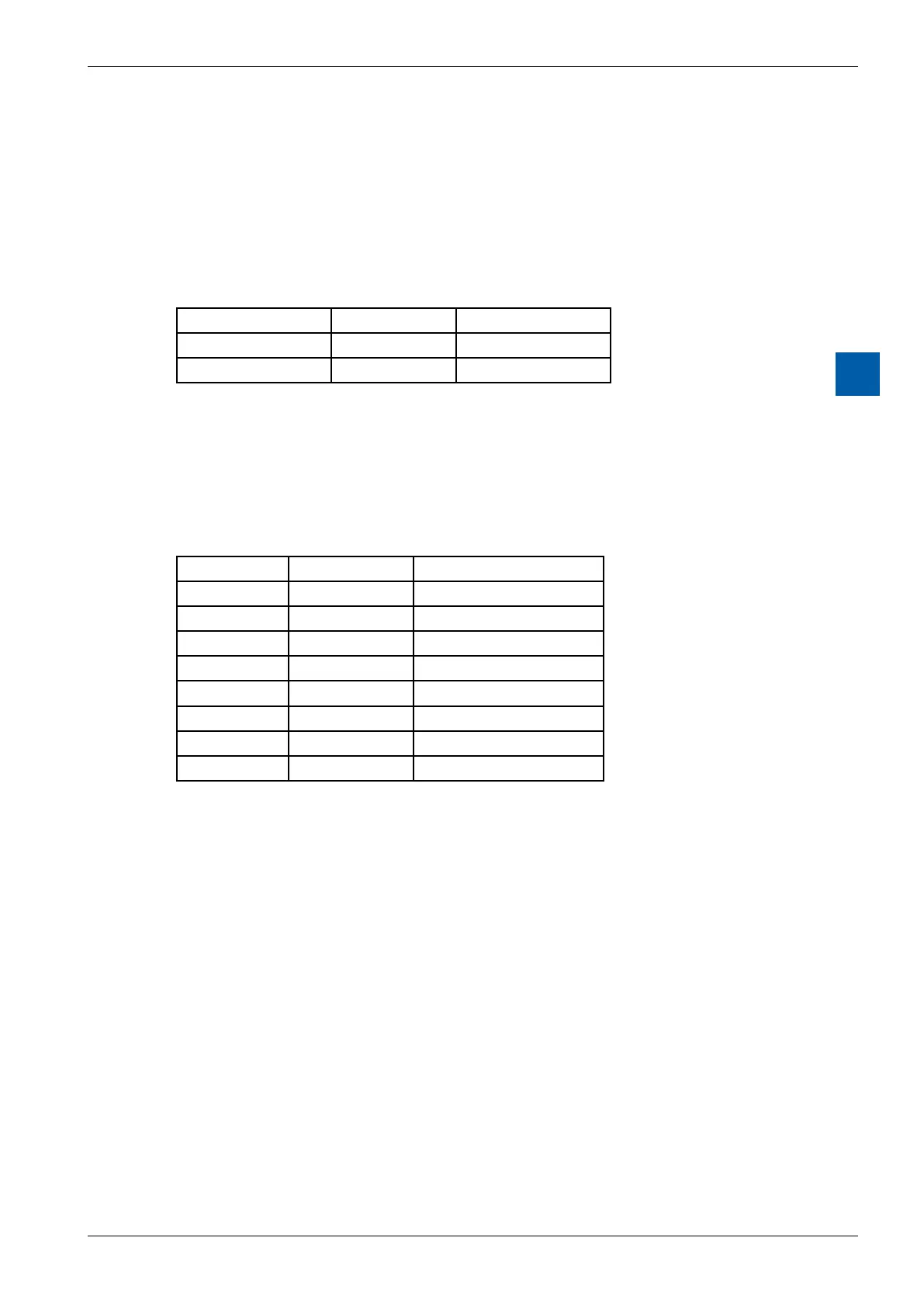
Signication of the I/O words of a PCD2/3.W525 module?
WhenconguringaW525moduleusingtheDeviceConguratororthePro-S-I/O
(orProbusDP)NetworkCongurator,thePCD2/3.W525doesneedtworegisters
for the analogue outputs and 8 registers for the analogue inputs.
Thesignicationsoftheregistersarethefollowing:
Output registers:
Register Bit 31…16 Bit 15…0
n Value CH0 Output
n+1 Value CH1 Output
Description of the output registers:
Value CH0..1 (Register n, n+1)
This registers (Bit 0 to 15) does contain the analogue output value of the corre-
sponding analogue output. It’s a 12 Bit value.
Input registers:
Register Bit 31…16 Bit 15…0
n Value CH0 Input
n+1 Value CH1 Input
n+2 Value CH2 Input
n+3 Value CH3 Input
n+4 Load Current/Voltage
n+5 Status Module
n+6 Status Input
n+7 Status Output
Description of the input registers:
Value CH0…CH3 (Register n…n+3)
This registers (Bit 0 to 15) does contain the analogue input value of the corre-
sponding analogue input. It’s a 14 Bit value.
Load_Current / Load_Voltage (Register n+4)
On this register (Bit 0 to 15) the actual current or voltage value is displayed.
■ currentin[μA](0…20’000)
■ voltage in [mV] (0…10’000)