Saia-Burgess Controls AG
Manual I/O-modules for PCD1 │ PCD2 series │ Document 27-600 – Release ENG09 │ 2019-05-01
5-104
I/O modules PCD1|PCD2
PCD2.W525 Combined analogue input/output module with galvanic isolation
5
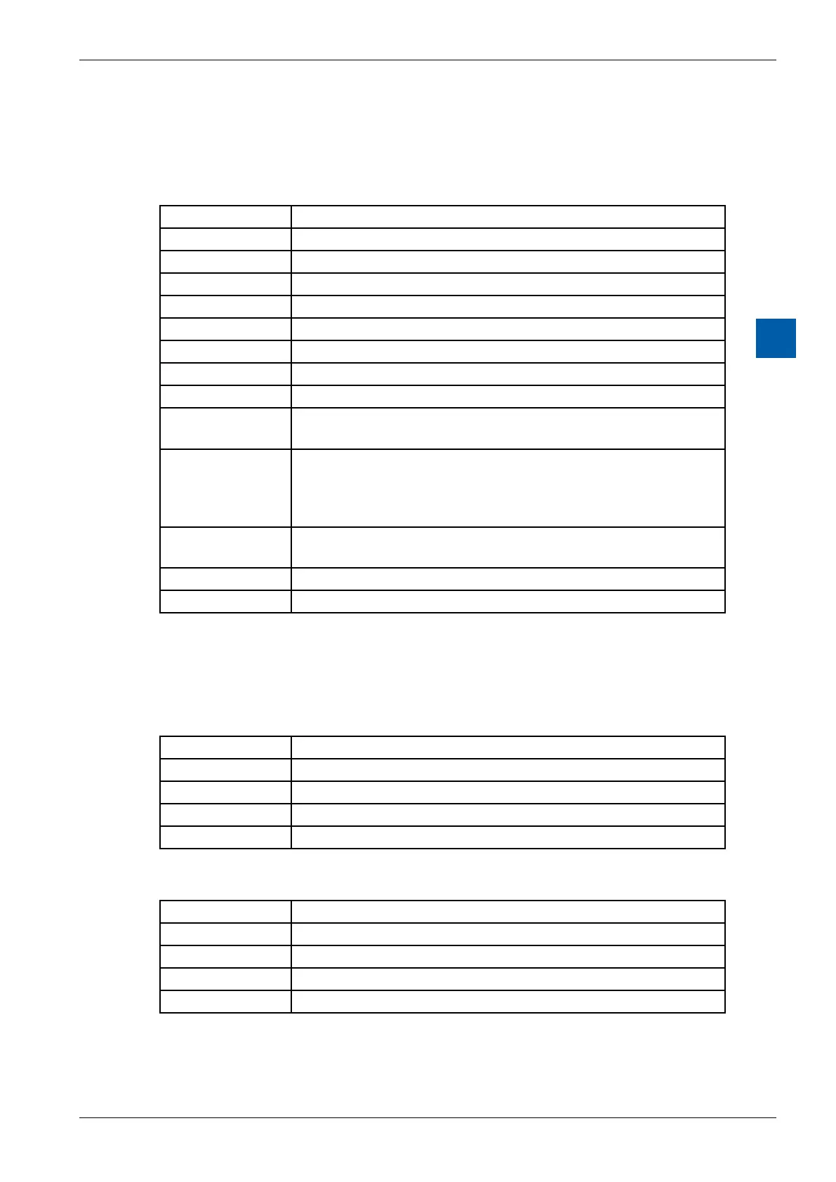
Status Module (Register n+5)
This register (Bit 0 to 15) does contain the actual status of the module
Table module status:
Bit Description
15:14 Reserved
13 Error on the output channel CH1
12 Error on the output channel CH0
11 Error on the input channel CH3
10 Error on the input channel CH2
9 Error on the input channel CH1
8 Error on the input channel CH0
7:5 Reserved
4 Communication: Illegal Command.
Is set to 1 if the module receive a not know instruction.
3 Communication: packet too long.
Is set to 1 if during the communication a data byte (CMD/
Data = 0) is received although a commando byte should be
received (CMD/Data = 1)
2 UExt too low.
The voltage of the external power supply is to low!
1 UExt Fail.
0 No Response.
Status Input (Register n+6)
This register (Bit 0 to 15) does contains the status of the input channels CH0..
CH3. The status of each input channel is displayed on 4 bits.
Status Input:
Bit Description
Bit 0…3 CH0 Status
Bit 4…7 CH1 Status
Bit 8…11 CH2 Status
Bit 12…15 CH3 Status
Table input status:
Bit Description
3 Over Temperature
2 Not Calibrated
1 Over Range
0 Under Range