Saia-Burgess Controls AG
Manual I/O-modules for PCD1 │ PCD2 series │ Document 27-600 – Release ENG09 │ 2019-05-01
5-122
I/O modules PCD1|PCD2
PCD2.H210
5
Voltage drop: max. 0.3 V at 500 mA
Output delay: < 1 µs, (longer for inductive load due to protective diode).
Power supply
Internal current consumption:
(from +5 V bus)
85 mA
Internal current consumption:
(from V+ bus)
0 mA
External current consumption: max. 2 A (all outputs), residual ripple max. 10 %
Operational conditions
Ambient temperature operation: 0 … +55°Cwithoutforcedventilation,
storage: -20 … +85°C
Noise immunity: EC mark according to EN 61 000-6-3 and EN 61 000-6-2
Programming: Based on Saia PCD
®
user program and pre-programmed
function blocks (FB).
Terminals: Pluggable 10-pole screw terminal block
(4 405 4847 0), for wires up to 1.5 mm²
*) For further information, please refer to manual 26/760, "PCD2.H210 - motion control
modules for stepper motors".
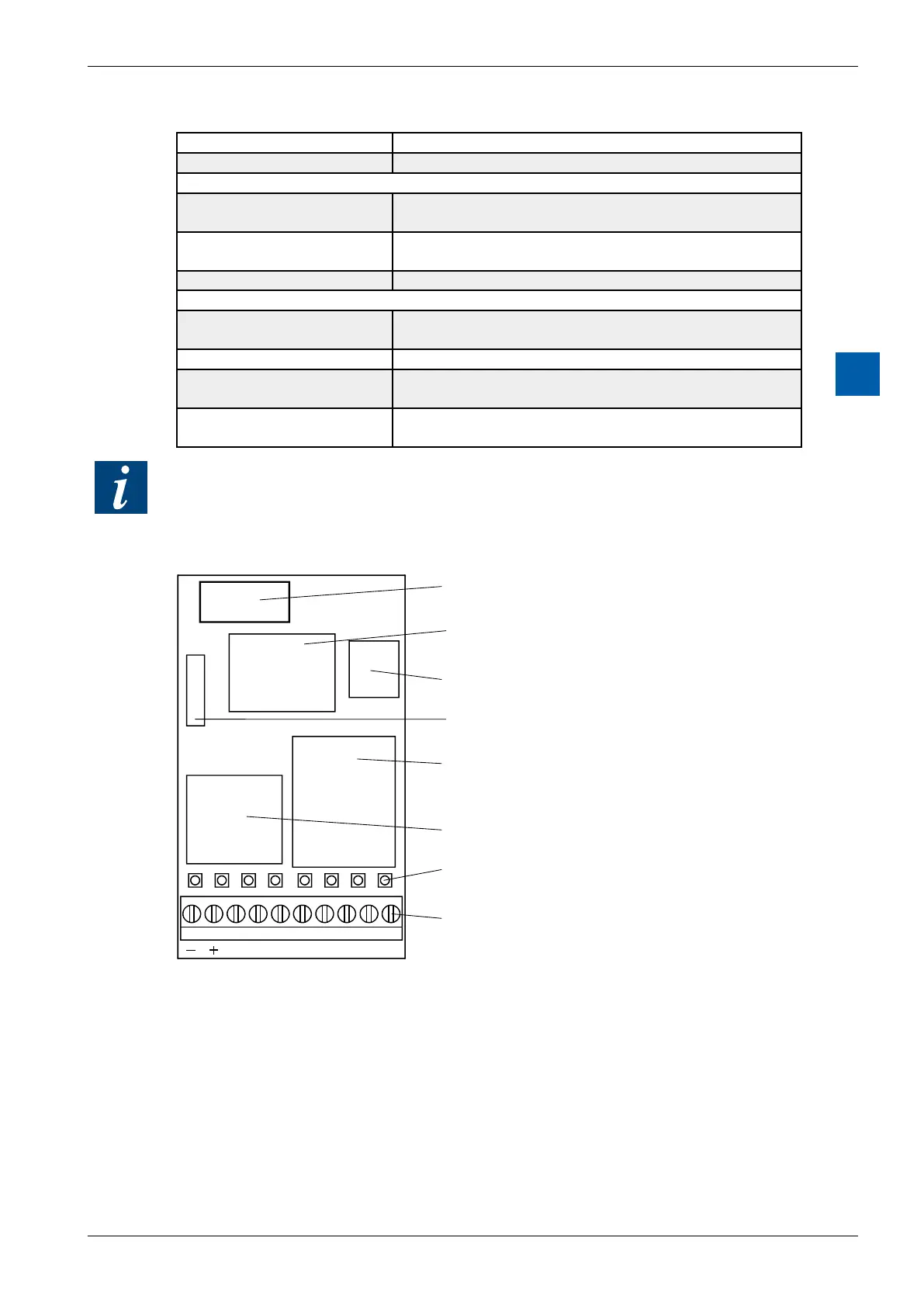
LEDs and connection terminals
9 8 7 6 5 4 3 2 1 0
A0
A1 E3 E2 E1 E0A2A3
FPGA
PROM on socket
Oscillator
Input filter
Output transistors
LEDs
Screw terminals
LED0:*)Voltageatinput0: (Emergencystop)
LED1:*)Voltageatinput1: (LS1)
LED2:*)Voltageatinput2: (REF)
LED3:*)Voltageatinput3: (LS2)
LED 4: Voltage at output 0: PUL
LED 5: Voltage at output 1: DIR
LED 6: Voltage at output 2
LED 7: Voltage at output 3
*)statusinvertedwhenusedasalimitswitch