Saia-Burgess Controls AG
Manual I/O-modules for PCD1 │ PCD2 series │ Document 27-600 – Release ENG09 │ 2019-05-01
6-57
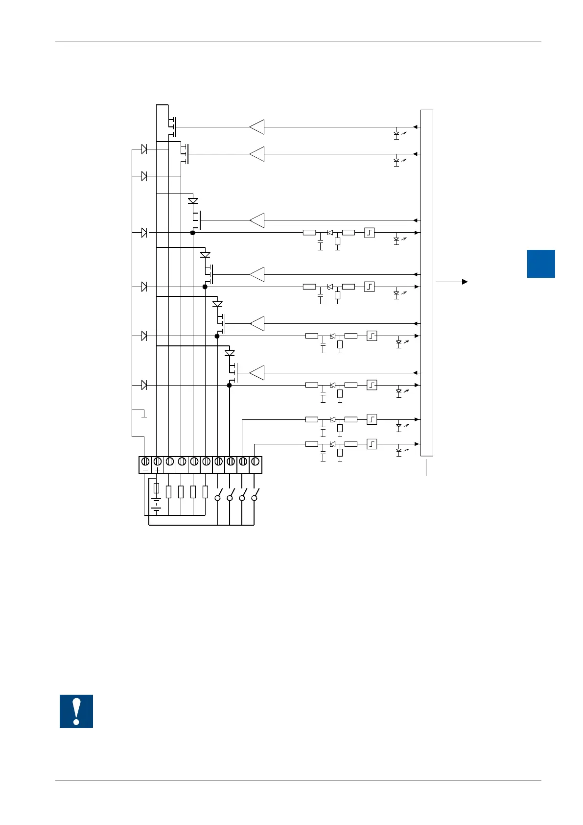
I/O modules PCD3
PCD3.B100
6
Input/output circuits and terminal designation
24 VDC
Fuse
The example shows I/O2 and I/O3 used as inputs and
I/O4 and I/O5 used as outputs
The following applies for the inputs:
Switch closed (input positive): Signal state = “1” = LED on
Switchopen: Signalstate=“0”=LEDo
Fuse: It is recommended that each module should be separately pro-
tected
with a fast-blow 3.15 A fuse.
Watchdog:Thismodulecanbeusedonallbaseaddresses;
there is no interaction with the watchdog on the CPUs.