Saia-Burgess Controls AG
Manual I/O-modules for PCD1 │ PCD2 series │ Document 27-600 – Release ENG09 │ 2019-05-01
6-67
I/O modules PCD3
PCD3.W3x0
6
Digital/analogue values
Input signals and type Digital values
PCD3.W300/W340 PCD3.W310/W340 PCD3.W340/50/60 Classic xx7 Simatic
+ 10.0 V + 20 mA Calculate the
appropriate values
with the formulae
at the end of this
section
4095 4095 27684
+ 5.0 V + 10 mA 2047 2047 13842
0 V 0 mA 0 0 0
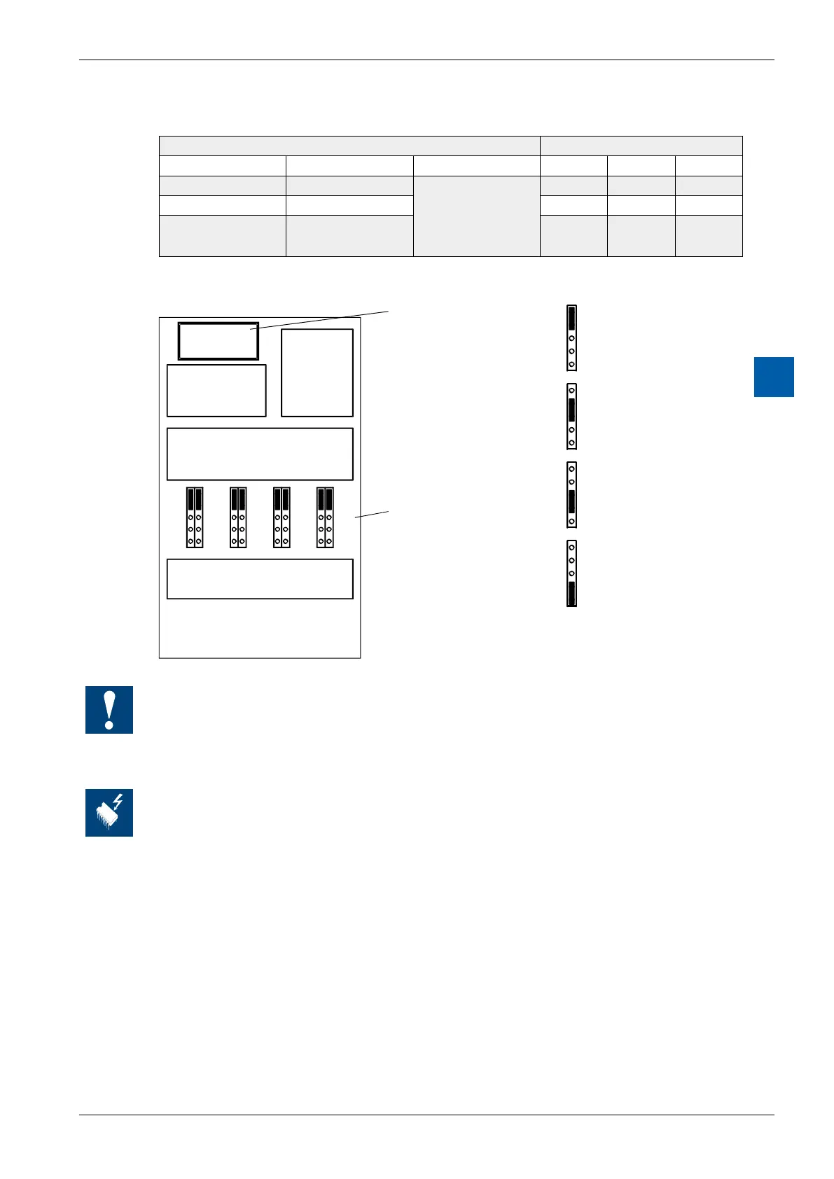
Layout (housing open, for instructions, see section 6.1.5)
ode selection
PCD3.W340 only)
T
/4
V
C
T
/4
V
C
T
/4
V
C
T
/4
V
C
Position 'T': Pt/Ni 1000
Position 'V/4': (0 .. +2.5V)
Position 'V': 0 .. +10V
Position 'C': 0 .. 20 mA
Jumper positions for selecting working mode
PCD3.W340only;ontheothermoduletypestheworkingmodesarexed
All inputs set for temperature (position T) must be wired. All unused inputs (with the W340)
must be adjusted to current range ‘C’ or voltage range ‘V’.
Changing the jumpers
On this circuit board there are components that are sensitive to electrostatic discharges. For
further information, refer to Appendix A1, "Icons"