Saia-Burgess Controls AG
Manual I/O-modules for PCD1 │ PCD2 series │ Document 27-600 – Release ENG09 │ 2019-05-01
6-68
I/O modules PCD3
PCD3.W3x0
6
Connection concept for voltage and current inputs
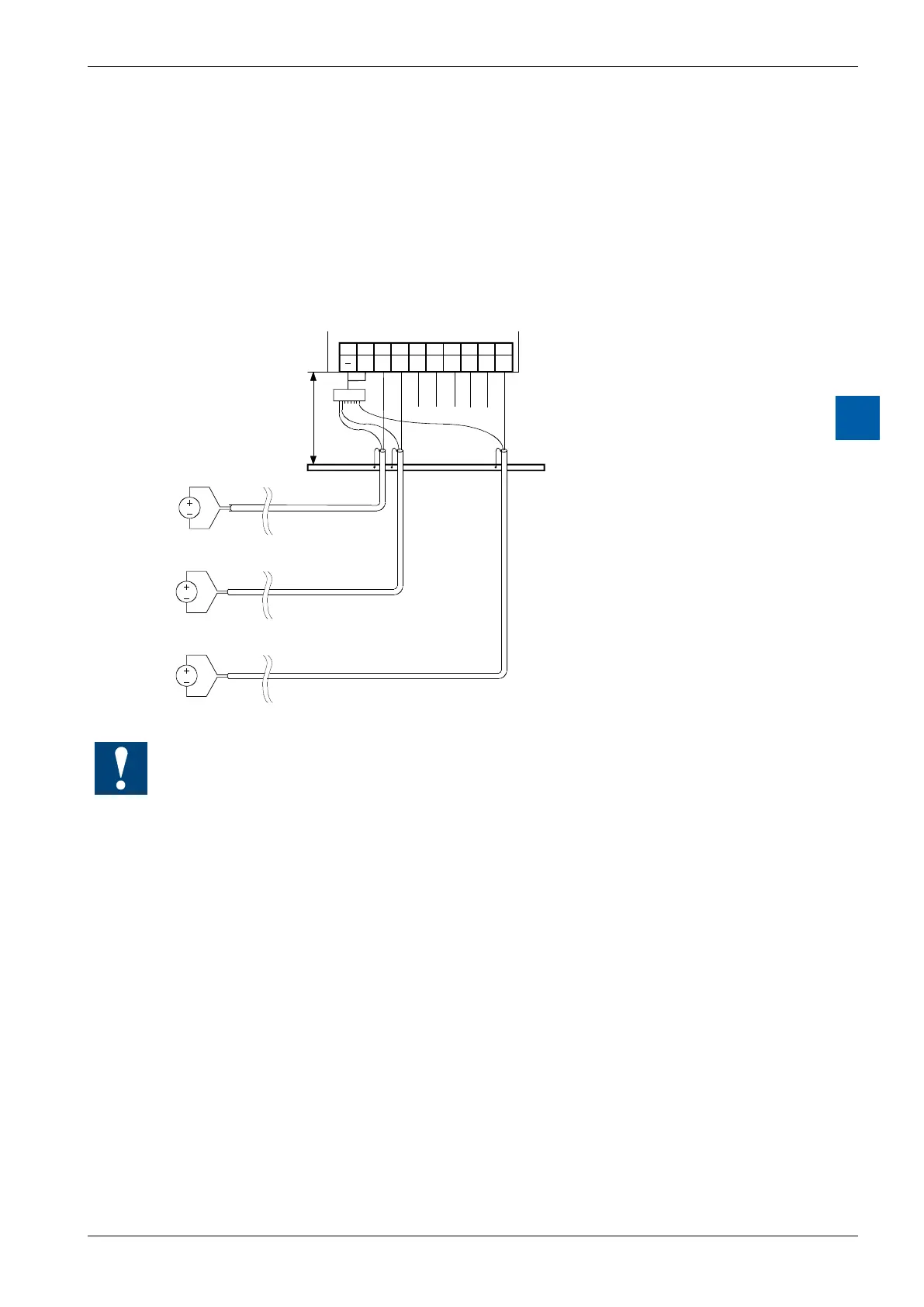
The voltage and current input signals are connected directly to the 10-pole
terminal block (E0…E7). To minimize the amount of interference coupled into the
module via the transmission lines, connection should be made according to the
principle explained below.
The following connection diagram shows a typical wiring layout for:
●voltage inputs with the PCD3.W300 and …W340 modules or
● currentinputswiththePCD3.W310and…W340modules
89
E 6
67
E 4
45
E 1
23
E 0
01
E 3 E 2E 5E 7
Earthing bar
max. 20cm
C O M
Distributor *)
● The reference potentials of signal sources should be wired to a common GND connec-
tion (“–” and “COM” terminals). To obtain optimum measurement results, any connection
to an earthing bar should be avoided.
● If screened cables are used, screening should be continued to an external earthing bar.