Saia-Burgess Controls AG
Manual I/O-modules for PCD1 │ PCD2 series │ Document 27-600 – Release ENG09 │ 2019-05-01
6-69
I/O modules PCD3
PCD3.W3x0
6
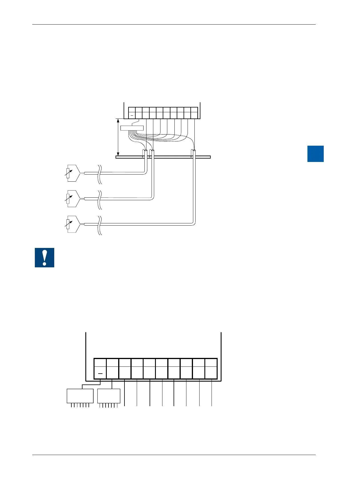
Connection concept for temperature sensors
The input signals for the temperature sensors are connected directly to the 10-pole
terminal block (I0 … I7).
The following connection diagram shows a typical layout for temperature sensors
with the PCD3.W340, …W350 and …W360 modules.
8 9
E6
6 7
E4
4 5
E1
2 3
E0
0 1
E3 E2 E5 E7
COM
Distributor *)
Earthing bar
max. 20 cm
*) potential free
● The reference potential for temperature measurements is the “COM” terminal,
which should not have any external earth or GND connection
● If screened cables are used, screening should be continued to an external earth-
ing bar
● Unused temperature inputs are to be connected to the "COM"
Mixed operation
89
E6
67
E4
4 5
E1
2 3
E0
0 1
E3 E2E5E7
COM
Distributor
‘V’ and ‘C’
Distributor
Temp.