Saia-Burgess Controls AG
Manual I/O-modules for PCD1 │ PCD2 series │ Document 27-600 – Release ENG09 │ 2019-05-01
6-76
I/O modules PCD3
PCD3.W3x5
6
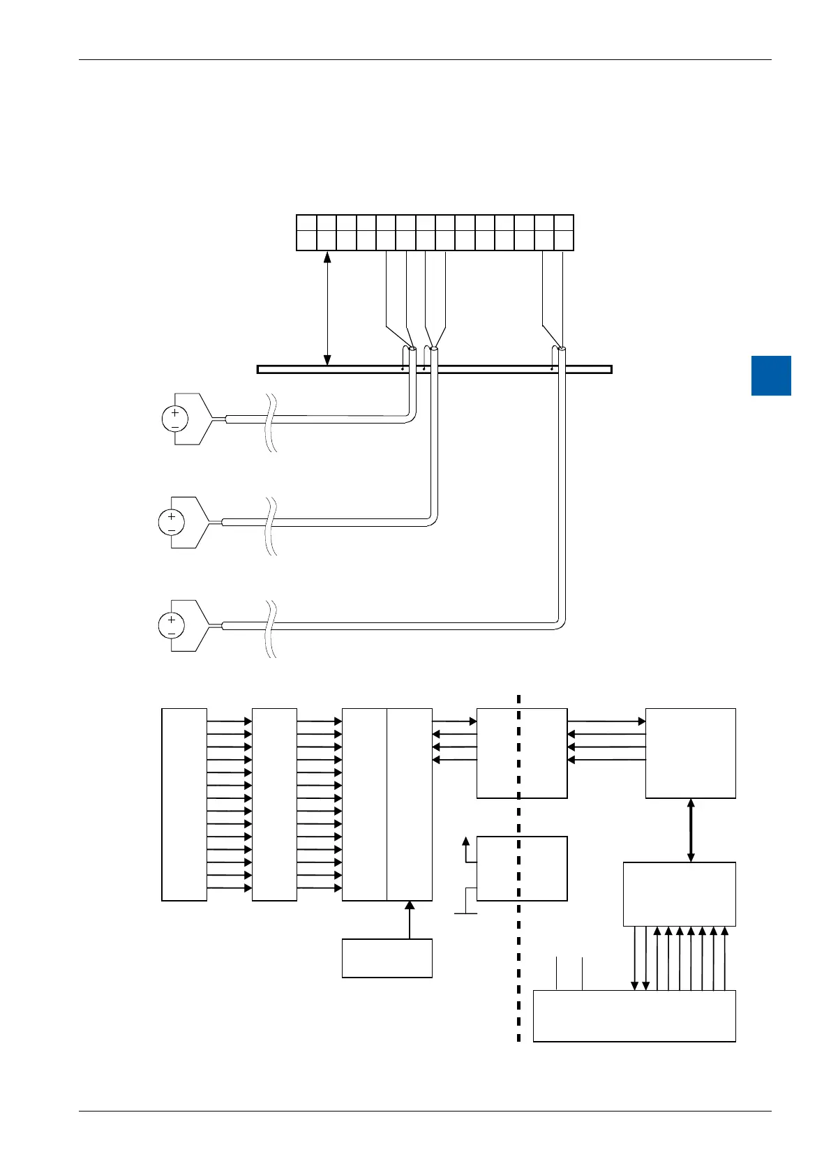
The diagram shows a typical wiring layout for:
●Voltage inputs for the PCD3.W305 and PCD3.W325 modules, or
current inputs for the PCD3.W315 module
●If shielded cables are used, the shield should be continued to an external
earthing bar.
max. 20cm
E0 E1 E2 E3 E4 E5 E6
COM COM COM COM COM COM COM
0 1 2 3 4 5 6 7 8 9 10 11 12 13
Earthing bar
Block diagram
E0
COM
E1
COM
E2
COM
E3
COM
E4
COM
E5
COM
E6
COM
Galvanic
separated
serial
Interface
Galvanic separation
VCC
COM
+5 V GND