Saia-Burgess Controls AG
Manual I/O-modules for PCD1 │ PCD2 series │ Document 27-600 – Release ENG09 │ 2019-05-01
6-85
I/O modules PCD3
PCD3.W6x0
6
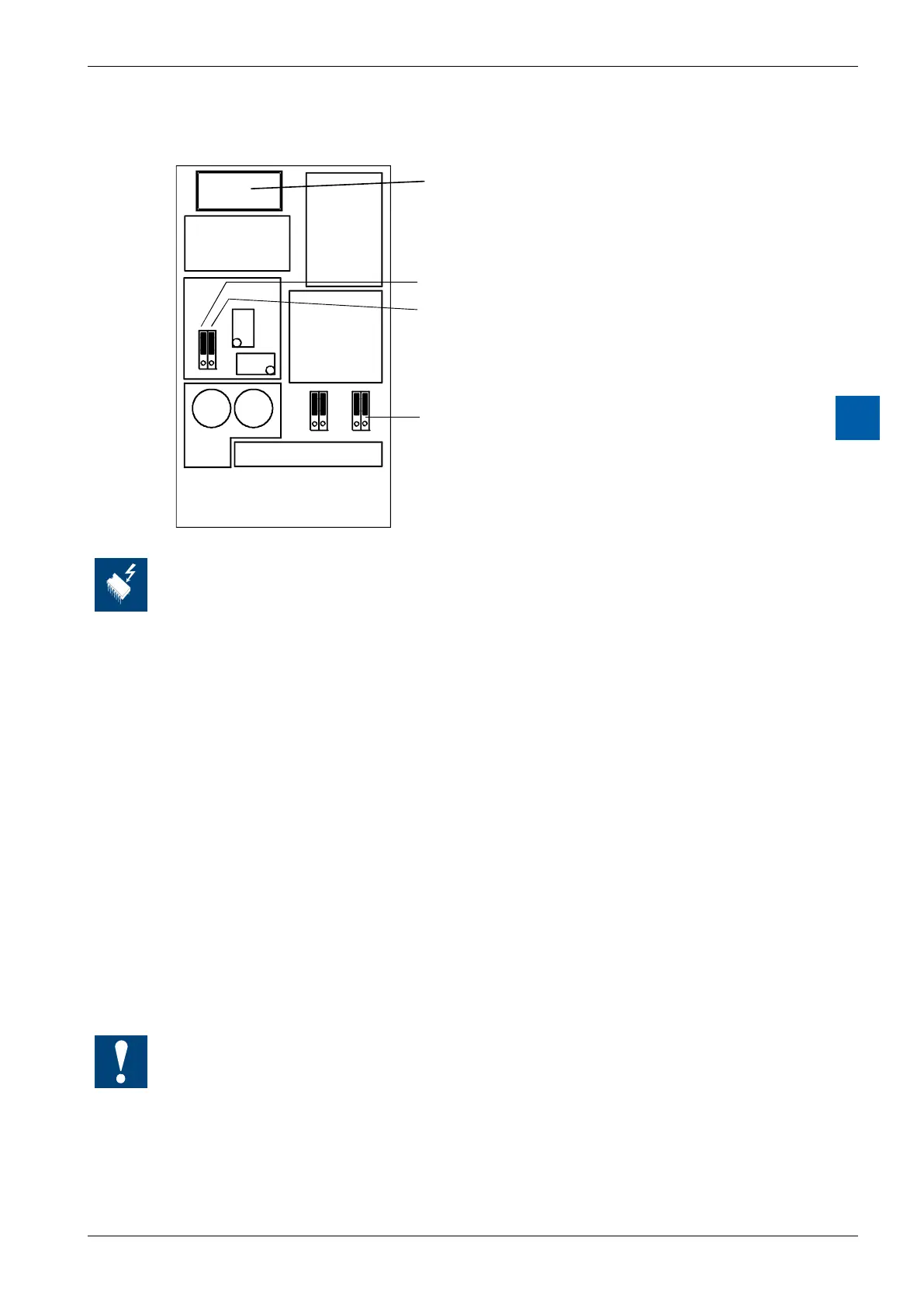
Layout (housing open, for instructions, see section 6.1.5)
Bus connector
Jumper ‘unipolar/bipolar’ (W610 only)
Jumper ‘voltage/current’ (W610 only)
Jumper ‘reset select’ (W610 only)
Changing the jumpers
On this circuit board there are components that are sensitive to electrostatic discharges. For
further information, refer to Appendix A1, "Icons"
Range selection(PCD3.W610)
Jumpers, factory settings: O0…O3: “V” (voltage)
U/B: “B” (bipolar)
Reset select: “mid“ (reset to mid-scale,
i.e. 0V in bipolar mode)
Ranges depending on application:
Per module: U/B: Unipolar or Bipolar operation
Reset select: Reset to low- or mid-
scale Rec. setting: Unipolar →low-scale
Bipolar → mid-scale
Per channel: “V” Voltage output:
0…+10 V or –10 V…+10 V
“C”: Current output: 0…20 mA
Current outputs have been laid out for unipolar mode. Bipolar mode is possible, but for the
negative half of this operation the output is 0 mA.