Saia-Burgess Controls AG
Manual I/O-modules for PCD1 │ PCD2 series │ Document 27-600 – Release ENG09 │ 2019-05-01
6-95
I/O modules PCD3
PCD3.W500
6
As the current consumption of this module is considerable, when using a number of them in
the same system, the total load for all modules must be taken into consideration..
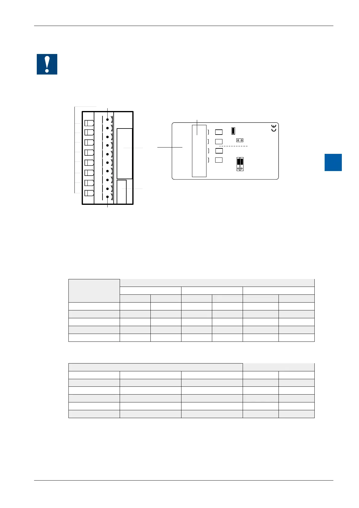
LEDs and connection terminals
0
1
2
3
4
5
6
7
LED 0...7 Terminal 0
Description
Label
Address
Label
- 10V +10V
0 - 10V
U
B
– 10V +10V
0 - 10V
B
U
B U
0
1
2
3
4
5
6
7
8
9
E0
–
E1
–
A0
–
A1
–
+
–
24VDC
PCD3.W500
2 out + 2 in voltage
Terminal 9
Terminal
W
5
0
0
The negative terminals “–” of outputs are connected internally to the ground, each
viaa100Ωresistor.
Analogue/digital values
Inputs
Input
signals
Digital values
Classic xx7 Simatic
unipolar bipolar unipolar bipolar unipolar bipolar
+10 V
4095
4095
4095
4095 27648 27648
+5 V
2047
3071
2047
3071 13824 13824
0 V
0
2047
0
2047 0 0
-5 V 0 1023 0 1023 0 -13824
–10 V 0 0 0 0 0 -27648
Outputs
Digital values Output signals
Classic xx7 Simatic unipolar bipolar
4095 4095 27648 +10.0 V +10.0 V
3071 3071 20736 +7.5 V +5.0 V
2047 2047 13824 +5.0 V 0 V
1023 1023 6912 +2.5 V -5.0 V
0 0 0 0 V –10.0 V