Saia-Burgess Controls AG
Manual I/O-modules for PCD1 │ PCD2 series │ Document 27-600 – Release ENG09 │ 2019-05-01
6-96
I/O modules PCD3
PCD3.W500
6
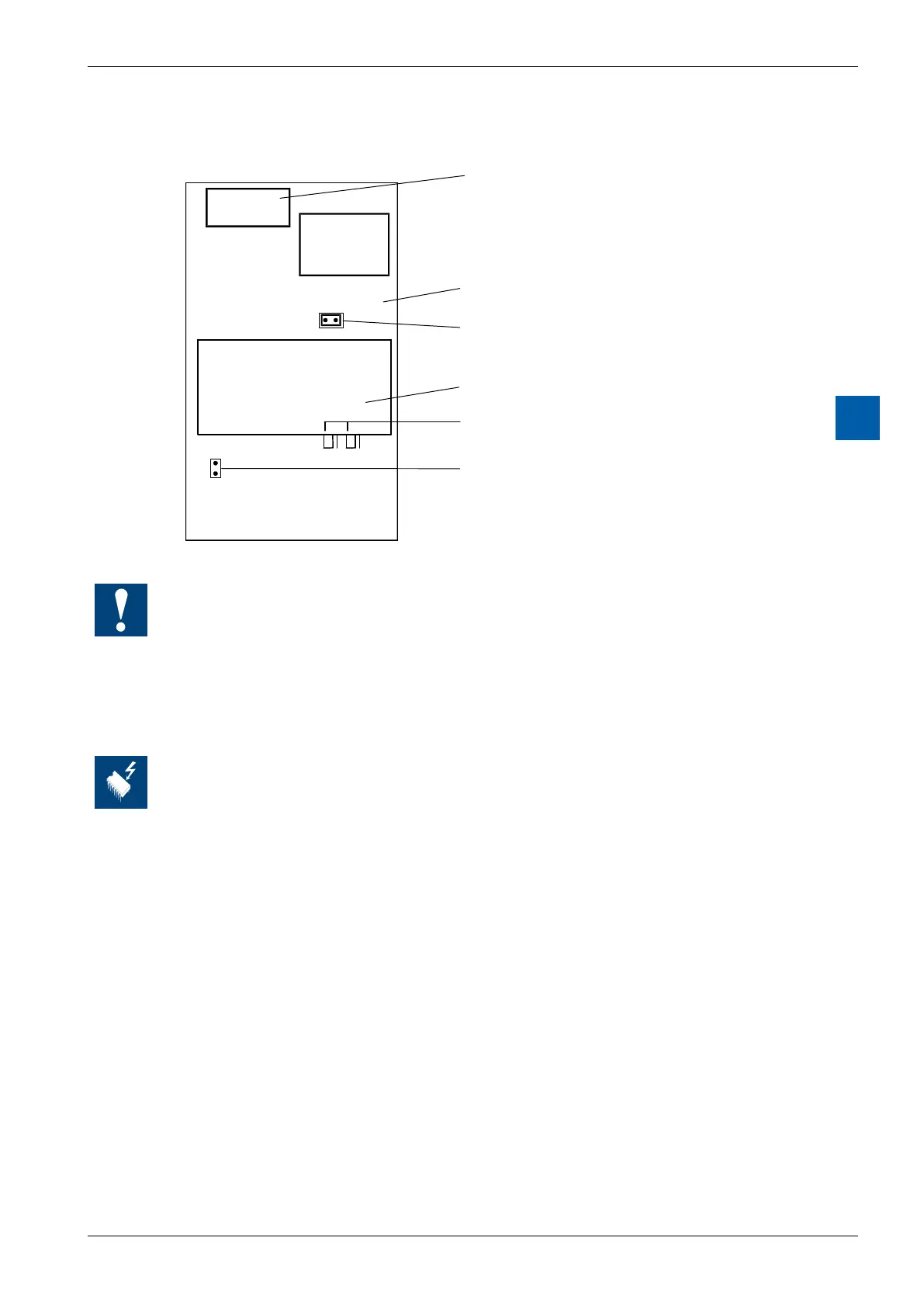
Layout (housing open, for instructions, see section 6.1.5)
U/B0 U/B1
Bus connector
Basic circuit board
Jumper: inputs, unipolar (U)
Plug-in module
Jumpers U/B 0 and U/B 1
on plug-in module
Jumper: inputs, bipolar (B)
PCD3.W500 module, fully equipped
(with additional module plugged on)
Apart from the bus connector, DC-DC converter and terminals, the base module carries the
two input channels with the 2-pole jumper for unipolar or bipolar operation and a number of
preset potentiometers, which cannot be adjusted by the user.
The plug-on module contains the two analogue outputs with the two 3-pole jumpers for the
individual unipolar or bipolar operation of each output.
The module also works without the plug-on module.
Changing the jumpers
On this circuit board there are components that are sensitive to electrostatic discharges. For
further information, refer to Appendix A1, "Icons"