Saia-Burgess Controls AG
Manual I/O-modules for PCD1 │ PCD2 series │ Document 27-600 – Release ENG09 │ 2019-05-01
5-20
I/O modules PCD1|PCD2
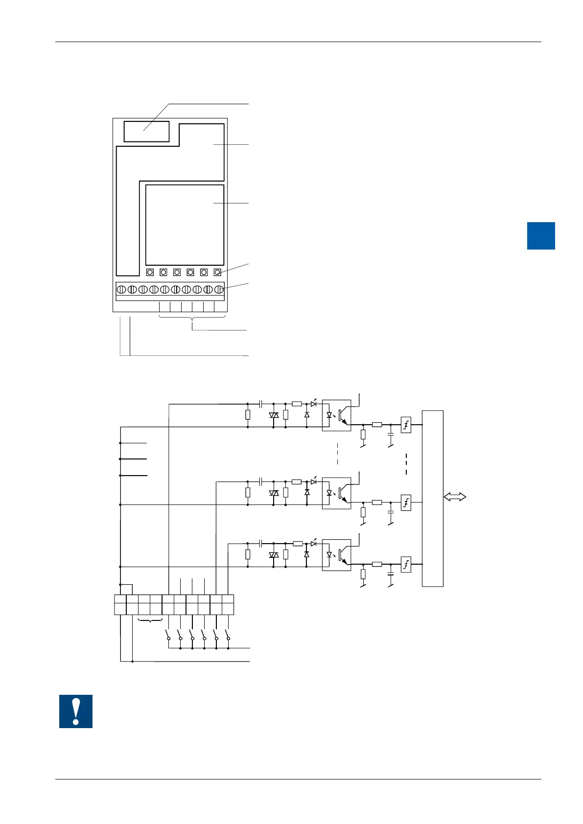
PCD2.E500
5
LEDs and connection terminals
9 8 7 6 5 4 3 2 1 0
E0E1E2E3E4E5COM COM
Bus interface,
Optocoupler,
threshold switch
Input bleeder chain
LEDs
Screw terminals
Inputs E0 to E5 0 - 5
Common connection
for the 6 inputs
Input circuits and terminal designation
Switch closed: Signal status 'H' = LED on
Switch open : Signal status 'L' = LED off
Phase 115 - 230V 50/60 Hz *)
*) or interchangeable, if the rules permit this
COM
COM
Watchdog:Thismodulecanbeusedonallbaseaddresses;thereisnointerac-
tion with the watchdog on the CPUs. For details, please refer to the section A4
“Hardware Watchdog”, which describes the correct use of the watchdog in con-
junction with PCD components.