Saia-Burgess Controls AG
Manual I/O-modules for PCD1 │ PCD2 series │ Document 27-600 – Release ENG09 │ 2019-05-01
5-58
I/O modules PCD1|PCD2
PCD2.W11x
5
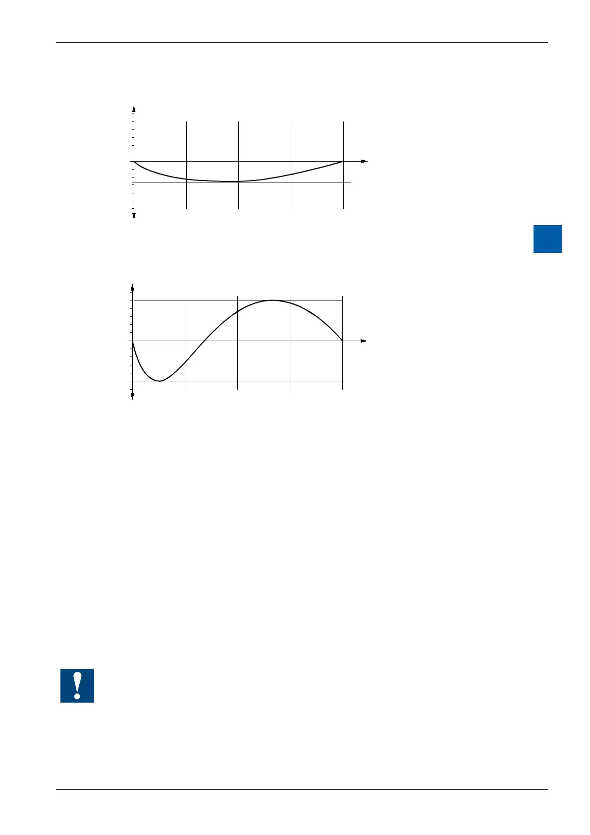
Typical linearity error for W110/112/114 (Pt 100/Pt 1000)
-50
0
0
1024
+50
2047.5
+100
3071
+150
4095
°C
LSB
Measurement
Deviation (LSB)
0
+1
+2
+3
+4
+5
+1
+2
+3
+4
+5
+6
+6
Typical linearity error for W111/113 (Ni 100/Ni 1000)
-50
0
0
1024
+50
2047.5
+100
3071
+150
4095
°C
LSB
Measurement
Deviation (LSB)
0
+1
+2
+3
+4
+5
+1
+2
+3
+4
+5
+6
+6
On cable break → Measurement 4095
On short circuit → Measurement 0
Base and variant modules
Each module comprises 2 individual modules.
● Basemodulewithinputlters,A/Dconverter,I/Oport.Samemodulewithsame
ttingsforall4variants.
● Plug-onvariantmoduleswithswitchingcircuittogenerate-15V,powersources
and linearization. Each of the four variants has a module of its own, i.e. a
modulewithdierentequipment.
Theuserhasaccesstothe4potentiometerstosettheosetforeachindividual
channel. This can be useful for adjusting the zero value (at -50 °C) for long
measurement cables.
All modules are set up in pairs (base and variant module) at the factory. The vari-
ant modules must not be exchanged.