Saia-Burgess Controls AG
Manual I/O-modules for PCD1 │ PCD2 series │ Document 27-600 – Release ENG09 │ 2019-05-01
5-75
I/O modules PCD1|PCD2
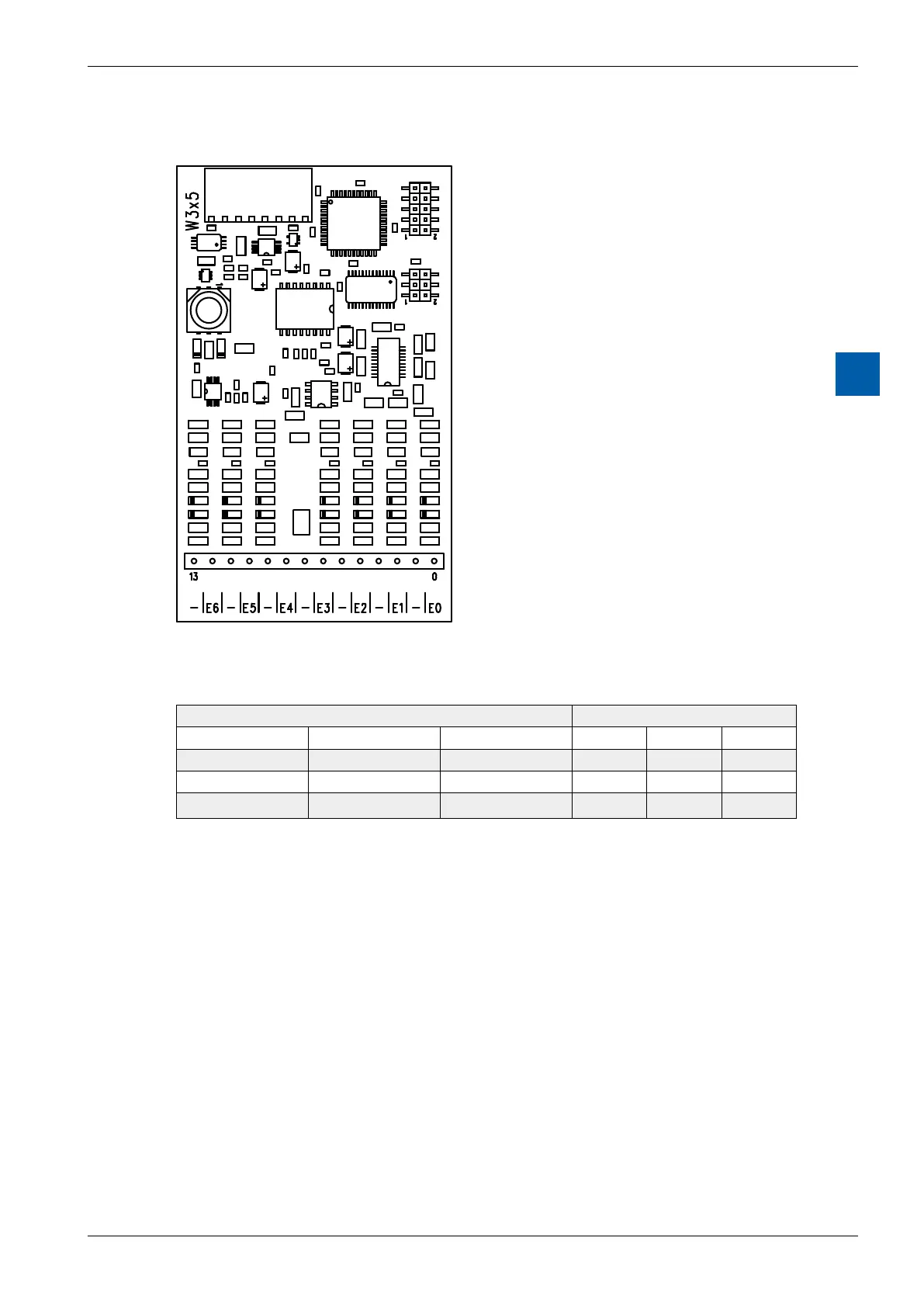
PCD2.W3x5
5
Terminals
Digital/analogue values
Input signals and type Digital values
PCD2.W305 PCD2.W315 PCD2.W325 Classic xx7 Simatic
+ 10.0 V + 20 mA +10 V 4095 4095 27684
+ 5.0 V + 10 mA 0 V 2047 2047 13842
0 V 0 mA –10 V 0 0 0
Connection concept for voltage and current inputs
The voltage and current input signals are connected directly to the 14-pole
terminalblock(E0 … E6andCOM).Tominimizetheamountofinterference
coupled into the module via the transmission lines, connection should be made
according to the principle explained below.