Saia-Burgess Controls AG
Manual I/O-modules for PCD1 │ PCD2 series │ Document 27-600 – Release ENG09 │ 2019-05-01
5-76
I/O modules PCD1|PCD2
PCD2.W3x5
5
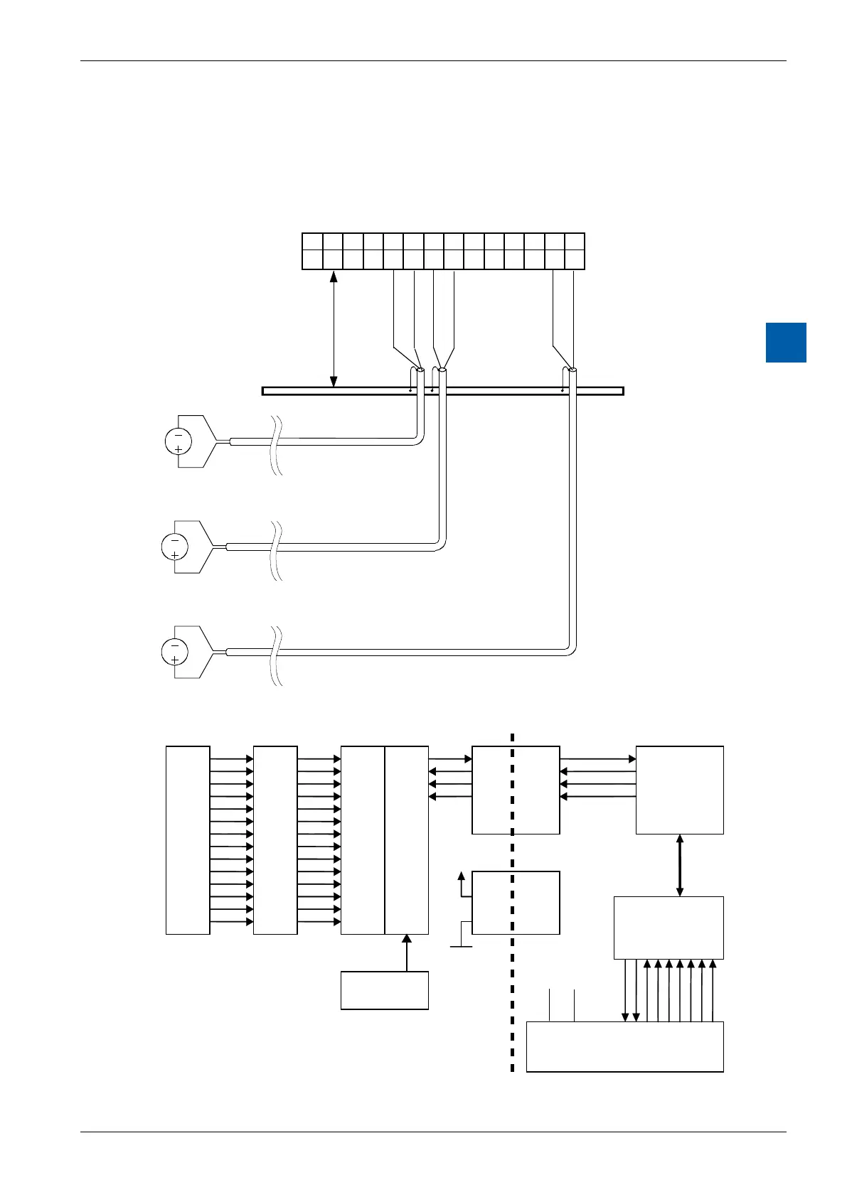
The following connection diagram shows a typical wiring layout for:
●Voltage inputs with the PCD2.W305 and .W325 modules or
● CurrentinputsforthePCD2.W315module
●If shielded cables are used, the shield should be continued to an external
earthing bar.
max. 20cm
E0E1E2E3E4E5E6
COMCOMCOMCOMCOMCOMCOM
012345678910111213
Earthing bar
Block diagram
E0
COM
E1
COM
E2
COM
E3
COM
E4
COM
E5
COM
E6
COM
Reference
Voltage 2.5V
μController
PCD Bus
I/O Bus
Galvanically
separate
interface
Electrically isolation
VCC
COM
+5 V GND
Programming