Saia-Burgess Controls AG
Manual I/O-modules for PCD1 │ PCD2 series │ Document 27-600 – Release ENG09 │ 2019-05-01
5-80
I/O modules PCD1|PCD2
PCD2.W4x0
5
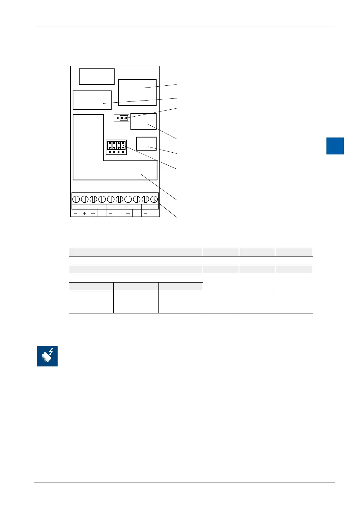
Terminals
2 3 1 0
V
C
4 0
A0 A1 A2 A3
9 8 7 6 5 4 3 2 1 0
Bus connector
Reference voltage
Bus interface
Offset-Jumper J1 (type PCD2.W410 only)
Position "0" : 0.to. 10 Vor 0.to. 20 mA
Position "4" : 2.to. 10 Vor 4.to. 20 mA
D/A converter
Output amplifier 0.to. 10 V
Jumper J2 for voltage/current
(type PCD2.W410 only)
Position "V" : Voltage output
Position "C" : Current output
External supply to V/C converter
(type PCD2.W410 only)
Screw terminals
Analogue/digital values and jumper positions
Jumper “V/C” V C C
Jumper “0/4” 0 0 4
Signal range 0 … 10V 0 … 20mA 4 … 20mA
Digital values
Classic xx7 Simatic
255
128
0
255
128
0
27648
13824
0
10.0 V
5.0 V*)
0
20 mA
10 mA*)
0
20 mA
12 mA*)
4 mA
*)Theexactvaluesare1/255higher
Changing the jumpers
On this circuit board there are components that are sensitive to electrostatic
discharges. For further information, refer to Appendix A1, “Icons”.