Saia-Burgess Controls AG
Manual I/O-modules for PCD1 │ PCD2 series │ Document 27-600 – Release ENG09 │ 2019-05-01
5-85
I/O modules PCD1|PCD2
PCD2.W6x0
5
Changing the jumpers
There are components on this circuit board, that are sensitive to electrostatic dis-
charges. For further information, refer to Appendix A1, “Icons”.
Range selection (PCD2.W610)
Jumpers,factorysettings: A0 … A3: “V” (voltage)
U/B: “B” (bipolar)
Reset select: “mid“ (reset to mid-scale,
i.e. 0 V in bipolar mode)
Ranges depending on application:
Per module: U/B: Unipolar or Bipolar operation
Reset select: Reset to low- or mid-scale
Rec. setting: Unipolar →low-scale
Bipolar → mid-scale
Per channel: “V” Voltage output:
0 … +10Vor–10V … +10V
“C”: Currentoutput: 0 … 20mA
Current outputs have been laid out for unipolar mode. Bipolar mode is possible,
but for the negative half of this operation the output is 0 mA.
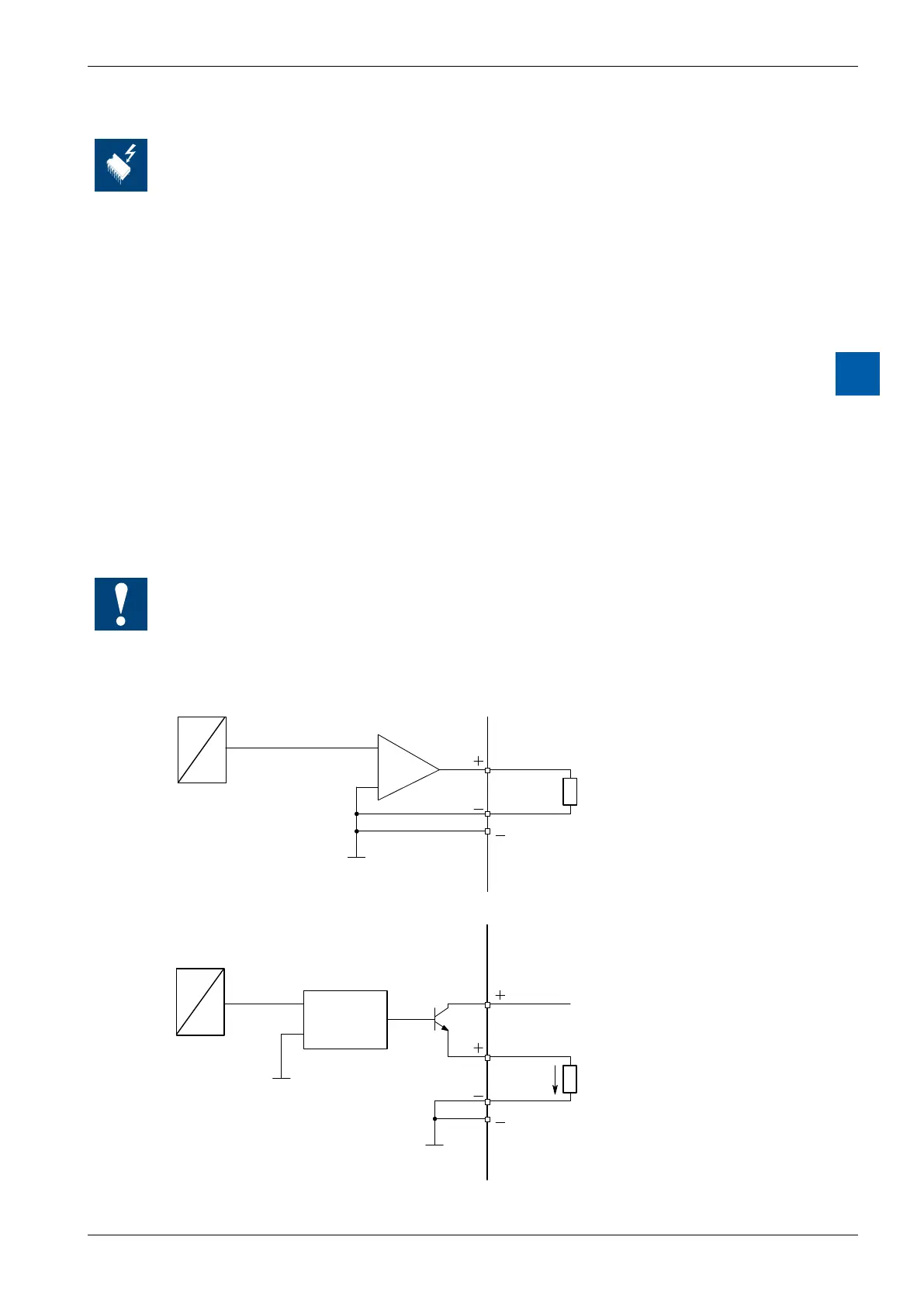
Connection concept
Connection for 0 … 10 V or –10 V … +10 V: (selectable on the PCD2.W610)
4 (A2)
Connection for 0 … 20 mA: (PCD2.W610 only)
4 (A2)
Contrôle de la
tension de la
source de
courant
An external 24 VDC supply is required for current outputs.