Analog input and output parameter group 02
PARAMETER DESCRIPTION 83
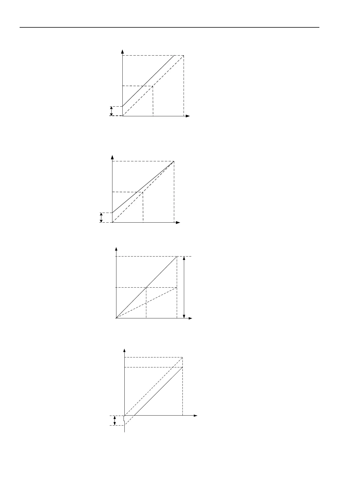
Example 2: This example is for users who need the motor to run at 10Hz when the potentiometer is turned to the
left end. All frequencies above 10Hz can still be adjusted by the user freely.
Max operation
frequency
Parameter setting
02-25(P.198)=0V02-
26( P.199)=8.33V Terminal 3-5
max/min positive voltage
02-27(P.196)=16.7%, 02-28(P.197)
=100% Percentage corresponds
to terminal 3-5 input voltage
02-27(P.196) =10Hz/ 60Hz * 100
02-26(P.199)= 10V *(100.0
P.196)/100
02-61(P.141)=0
0V 5V 10V
0Hz
60Hz
30Hz
10Hz
Bias
adjust
02-20(P.17)= 1 Select voltage signal
02-21(P.39) = 60Hz Max operation
frequency
Voltage
Example 3: This example is also frequently used by the industry. The comprehensive usage for all domain of the
potentiometer setup elevates the flexibility.
Max operation
frequency
Parameter setting
02-21P.39 = 60Hz Max operation frequency
02-61P.141 = 0
0V
5V 10V
0Hz
60Hz
30Hz
10Hz
Bias
adjust
02-20P.17 = 1 Select voltage signal
02-25P.198=0V, 02-26P.199=10V
Terminal 3-5 max/min positive voltage
02-27P.196=16.7%, 02-28P.197
=100% Percentage corresponds to terminal
3-5 input voltage
02-27P.196 = 10Hz / 60Hz * 100
Voltage
Example 4: This example uses 0~5V to give frequency command.
5V
2.5V
0V
30Hz
60Hz
0Hz
Gain adjustment
Parameter setting
02-21P.39 = 60.00Hz Max operation
frequency
02-20P.17 = 1 Select voltage signal
02-61P.141 = 0 02-25P.198=0V,
02-26P.199=5V Terminal 3-5 max/
min positive voltage
02-27(P.196)=0%,02-28(P.197)=100%
Percentage corresponds to terminal 3-5
input voltage
Max operation
frequency
Voltage
Example 5: This example is used to avoid signal below 1V given to inverter as running frequency in harsh
environment, which can greatly avoid the interference of noise.
10V
1V
0V
54Hz
60Hz
0Hz
Parameter setting
02-21P.39 = 60.00Hz Max operation
frequency
02-20P.17 = 1 Select voltage signal
02-61P.141 = 0
Max operation
frequency
6Hz
Negative
bias
6Hz
02-25P.198=1V, 02-26P.199
=10V Terminal 3-5 max/min positive
voltage
02-26P.196=0%,02-27 P.197
=90% Percentage corresponds to
terminal 3-5 input voltage
02-27P.197 = 100.0( 1V /
10V ) * 100
Voltage
Example 6: This example is an extension of Example 5. This kind of application is open, user can apply flexibly.

 Loading...

