Analog input and output parameter group 02
PARAMETER DESCRIPTION 82
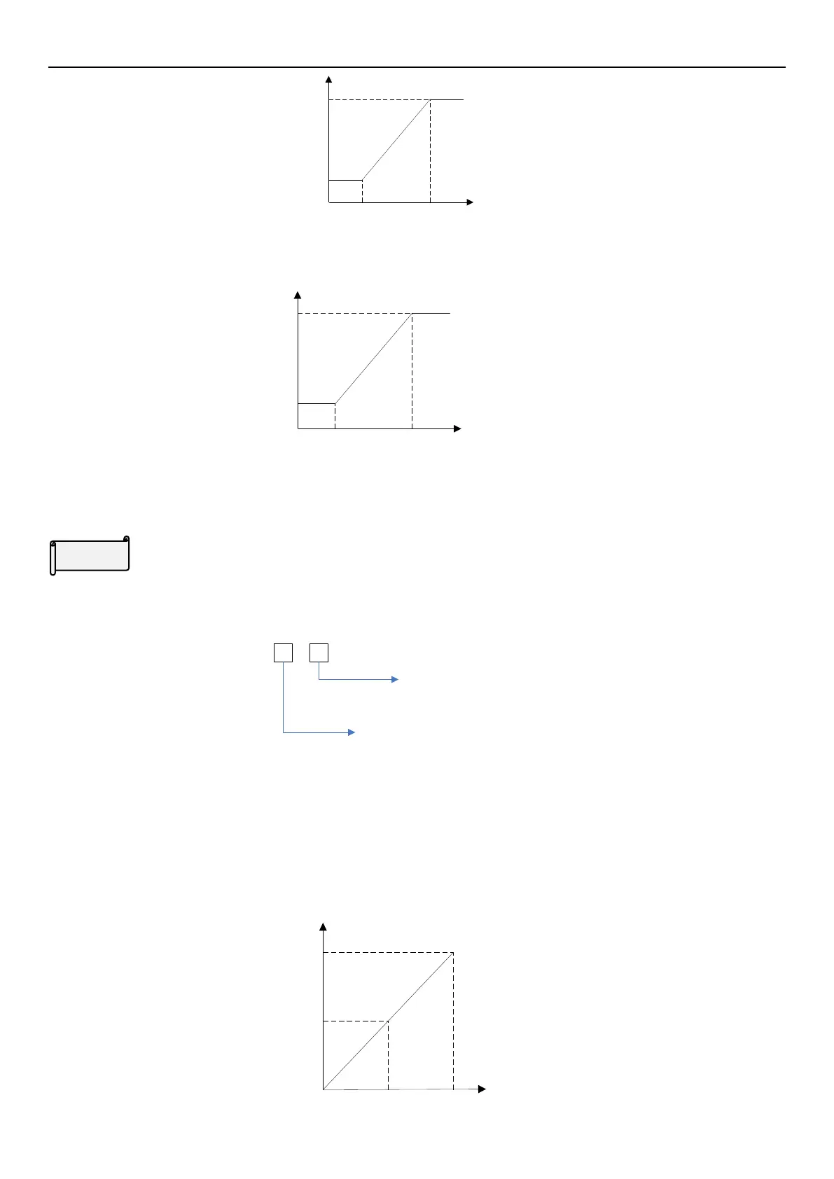
A value
B value
02-27
(P.196)
02-28
(P.197)
Terminal 3-5 signal
%
Example 1.2: Set 02-27(P.196) and 02-28(P.197) value, then set 02-25(P.198) and 02-26(P.199). Figure is shown
as follows:
02-25
(P.198)
02-26
(P.199)
02-27
(P.196)
02-28
(P.197)
Terminal 3-5 signal
%
If the external analog frequency is selected, the ratio calculated according to the figure above is multiplied by
02-21 (P.39) to be the actual frequency input value ( terminal 3-5 current/voltage input corresponding percentage
selections are all positive 02-61( P.141) = 0).
Polarity of percentage corresponds to terminal 3-5 current/ voltage signal
The setting of parameter 02-61 (P.141) is set in bits, a total of 2 bits, the meaning of each bit is as follows:
02-61
P.141=
0: Parameter 02-27(P.196) value
is for positive
1: Parameter 02-27(P.196) value
is for negative
0: Parameter 02-28(P.197) value is for positive
1: Parameter 02-28(P.197) value is for negative
If the input percentage of the given current/voltage is negative, the inverter runs in the reverse direction of the given
running direction.
Some application examples of terminal 3-5
Example 1: This example is the most commonly used method. It is used when inverter is in “external mode",
“combined mode 2”or “combined mode 4”, and frequency command is given by terminal 3-5.
0V
Max operation
frequency
60Hz
30Hz
0Hz
5V 10V
Parameter setting
02-21P.39 = 60Hz Max
operation frequency
02-20P.17 = 1 Select
voltage signal
02-61P.141 = 0
Voltage

 Loading...

