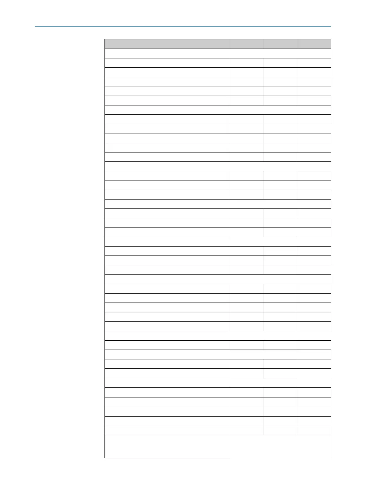
Minimum Typical Maximum
FE screw terminal technical data
Rigid wire cross-circuit 0.3 mm² 1.6 mm²
Flexible wire cross-circuit
6)
0.3 mm² 1.6 mm²
American wire gage (AWG) 22 14
Wire stripping length 5 mm
Screw tightening torque 0.5 Nm
Screw terminal technical data
Rigid wire cross-circuit 0.14 mm² 1.5 mm²
Flexible wire cross-circuit
7)
0.14 mm² 1.0 mm²
American wire gage (AWG) 26 16
Wire stripping length 5 mm
Screw tightening torque 0.22 Nm 0.3 Nm
Cable length for power supply tolerance ± 10%
At wire cross-section 1 mm² 50 m
At wire cross-section 0.5 mm² 25 m
At wire cross-section 0.25 mm² 12 m
Cable length for power supply tolerance ± 5%
At wire cross-section 1 mm² 60 m
with a wire cross-section of 0.5 mm² 30 m
with a wire cross-section of 0.25 mm² 15 m
Cable length for power supply tolerance ± 1%
At wire cross-section 1 mm² 70 m
with a wire cross-section of 0.5 mm² 35 m
with a wire cross-section of 0.25 mm² 17 m
UNI-I/O1 and UNI-I/O2
Input resistance at HIGH 2 kΩ
Voltage for HIGH 11 V 24 V 30 V
Voltage for LOW –3 V 0 V 5 V
Input capacitance 15 nF
Static input current 6 mA 15 mA
When used for Reset
Actuating time of the control switch 200 ms
When used for EDM
Permissible contactor dropout time 300 ms
Permissible contactor pull in time 300 ms
UNI-I/O3, UNI-I/O4 and UNI-I/O5
Switching voltage HIGH at 200 mA U
V
– 3.3 V U
V
Source switching current 100 mA 200 mA
Current limiting (after 5 ms at 25 °C) 600 mA 920 mA
Switch-on delay 1.4 ms 2 ms
Switch-off delay 0.7 ms 2 ms
Response time UNI<I/O3, UNI<I/O4 and
UNI<I/O5 on c
onfiguration as warning field out‐
put
Corresponds to the resulting response
time of the OSSDs plus 50 ms
12 TECHNICAL DATA
124
O P E R A T I N G I N S T R U C T I O N S | S300 8010948/ZA21/2020-06-18 | SICK
Subject to change without notice

 Loading...


