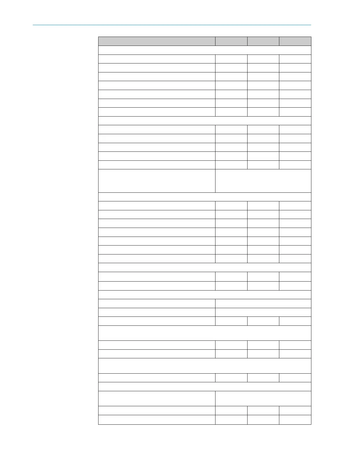
Minimum Typical Maximum
Standby mode input
Input resistance at HIGH 2 kΩ
Voltage for HIGH 11 V 24 V 30 V
Voltage for LOW –3 V 0 V 5 V
Input capacitance 15 nF
Static input current 6 mA 15 mA
Standby mode activation 80 ms
Standby mode deactivation 200 ms 250 ms
Static control inputs
Input resistance at HIGH 2 kΩ
Voltage for HIGH 11 V 24 V 30 V
Voltage for LOW –3 V 0 V 5 V
Input capacitance 15 nF
Static input current 6 mA 15 mA
Input frequency (max. switching sequence or fre‐
q
uency)
1/t
UFVz
+ half basic response time
(t
UFVz
= time set for advancing the timing
for the switching)
Dynamic control inputs
Input resistance at HIGH 2 kΩ
Voltage for HIGH 11 V 24 V 30 V
Voltage for LOW –3 V 0 V 5 V
Input capacitance 1 nF
Static input current 6 mA 15 mA
Duty cycle (Ti/T) 0.5
Input frequency 100 kHz
Voltage supply for incremental encoders
24 V voltage output U
V
– 3 V U
V
Current load per incremental encoder 50 mA 100 mA
Speed range that can be sampled
Forward From +10 cm/s to +2,000 cm/s
Backward From –10 cm/s to –2,000 cm/s
Speed tolerance with same direction information 45%
Tolerance time for exceeding speed with same direction information from the incremental
enc
oders
At < 30 cm/s 60 s
At ≥ 30 cm/s 20 s
Tolerance time for different direction information or signal failure from an incremental
enc
oder
At > 10 cm/s 0.4 s
Incremental encoders that can be evaluated
Type Dual-channel rotary encoder with 90°
pha
se shift
Enclosure rating IP54
Supply voltage U
V
– 3 V U
V
TECHNICAL DATA 12
8010948/ZA21/2020-06-18 | SICK O P E R A T I N G I N S T R U C T I O N S | S300
125
Subject to change without notice
 Loading...


