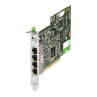
Installation and Circuitry
SICAM A8000 / CP-8000 • CP-8021 • CP-8022 Manual Unrestricted 209
DC8-037-2.02, Edition 10.2017
Interfaces at the Front
SD card X4: Ethernet
-
-
1 2 3 4 5 6 7 8
TXD+……………… Transmit Data +
TXD-………………. Transmit Data -
RXD+……………… Receive Data +
RXD-………………. Receive Data -
Interfaces at the Bottom
The process signals are to be connected to screw terminals. The pin assignment of the pe-
ripheral connectors is described in the following table.
X31 X32 X33 DI-8100
ed
1 2 3 4 5 6 7 8 9 1 2 3 4 5 1 2 3 4
X21 X22 X23 X24 DO-8203
T D06
1 2 3 4 1 2 3 4 1 2 3 4 1 2 3 4
X11 X12 X13 X14 PS
-
-
-
rved
1 2 3 1 2 3 4 1 2 3 4 5 1 2
IN D00 to IN D07…………… binary inputs of group 0, inputs 0 to 7
IN D10 to IN D13…………… binary inputs of group 1, inputs 10 to 13
COM IN 00…………………… common/supply of group 0
COM IN 10…………………… common/supply of group 1
OUT D00 to D07…………… make contact outputs 0 to 7
COM OUT D00 to D07…….. common (root) outputs 0 to 7
BAT+/-………………………… input voltage
AUX V0+/-……………………. voltage distribution
 Loading...


