Engineering via SICAM TOOLBOX II
302 Unrestricted SICAM A8000 / CP-8000 • CP-8021 • CP-8022 Manual
DC8-037-2.02, Edition 10.2017
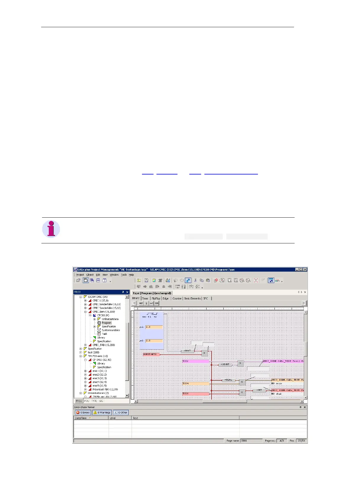
8.2.1 Creating a Function Diagram with CAEx plus
For the creation of a function diagram (FUD) the tool “CAEx plus” is required. This provides
various editors and standard libraries for the creation of the open-/closed-loop control function.
The process-technical functions of a plant are created with the function diagram editor (FBD
Editor). A function diagram is thereby created by the interconnection of
• predefined functions and function blocks (CP-8000/CP-802x library)
• functions and function blocks defined by the user
You find the description of the editor in the CAEx plus Online Help, chapter “Editors”.
Additional information can be found in the SICAM TOOLBOX II Online Help, chapter “Tutori-
als”, section “CAEx plus”.
You find the most important characteristic values (limits) for the creation of the open-/closed-
loop control function in section 5.4.1, CP-8000 and 5.4.2, CP-8021 and CP-8022.
You find the technical details for the processing of the open-/closed-loop control function and its
partial functions in the manual SICAM RTUs Common Functions System and Basic System
Elements, chapter “Automation”, section “Restricted Open-/Closed-Loop Control Function”,
“Application Program” | ”Function Diagram”.
Note
Optionally to the creation of a function diagram, an instruction list (IL) with ASCII format can be imported in
“CAEx plus” (tool “OPM II”, context menu of the CPU, Instruction list | Import from file ).
Function Diagram (Example)