Functions
2.20 Out-of-Step Protection (ANSI 78)
SIPROTEC, 7UM62, Manual
C53000-G1176-C149-7, Release date 03.2010
166
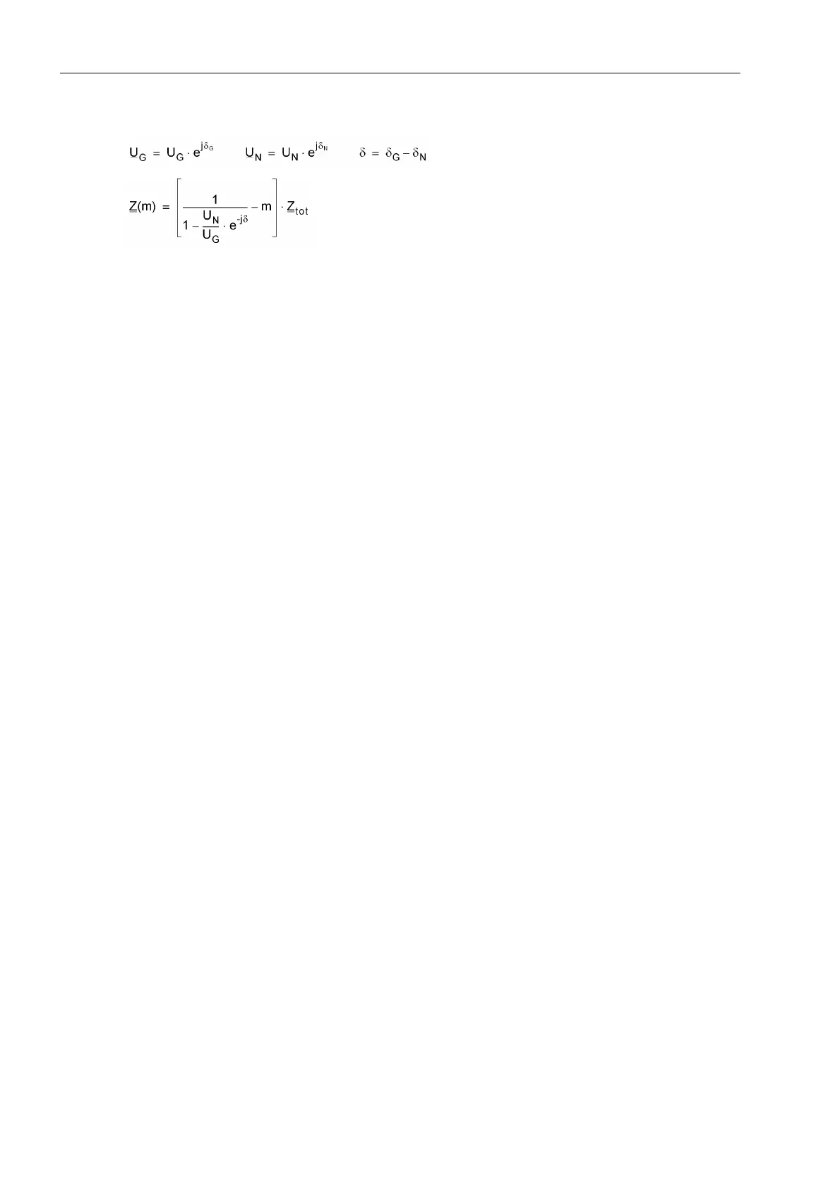
Thus, this results in:
where δ is the phase shift angle between the generator voltage and the network equivalent voltage. Under
normal conditions, this angle depends on the load situation and is largely constant. In the event of an out-of-
step condition, however the angle fluctuates continually and can vary between 0° and 360°. The following figure
shows the impedance vector trajectory at measurement location m in accordance with the above formula. The
coordinate system origin corresponds to the measurement location (voltage transformer set). When the ratio
of the voltage magnitudes U
N
/U
G
is kept constant and the load angle δ varies, then circular trajectories result.
The centre and the radius of the circle are determined by the ratio U
N
/U
G
. The centre points of the circles are
all on an axis line which is determined by the direction of Z
tot
. Minimum and maximum of the measured imped-
ance magnitude are at δ = 0° and δ = 180°. If the measurement location is at the electrical system centre, mea-
sured voltage and thus measured impedance become zero when δ = 180°.
Power Swing Polygon
The measurement characteristic is a power swing polygon adjustable in all four directions and in its inclination
angle ϕ
P
. This ensures optimum matching to the conditions in the power system.

 Loading...


