Functions
2.26 Rate-of-Frequency-Change Protection df/dt (ANSI 81R)
SIPROTEC, 7UM62, Manual
C53000-G1176-C149-7, Release date 03.2010
196
Time Delays
The delay time should be set to zero wherever the protection function is supposed to respond very quickly. This
will be the case with high setting values. For the monitoring of small changes (< 1Hz/s), on the other hand, a
small delay time can be useful to avoid overfunctioning. The delay time for stage 1 is set at address 4504 T
df1/dt, and the time set there is added to the protection operating time.
Release by the Frequency Protection
The parameter df1/dt & f1 (Address 4505) is used to set the release of the stage from a certain frequency
threshold on. For this the pertinent frequency stage of the frequency protection is queried. In the setting
example this is stage f1. To exclude coupling of the two functions, the parameter can be set to OFF (default
setting).
Advanced Parameters
The advanced parameters allow setting each for two stages (e.g. df1/dt and df2/dt) the dropout difference and
the measuring window. This setting can only be done with the DIGSI communication software.
Setting changes are necessary e.g. to obtain a large dropout difference. For the detection of very small fre-
quency changes (< 0.5 Hz/s), the default setting of the measuring window should be extended. This is to
improve the measuring accuracy.
Minimum Voltage
Address 4518 U MIN is used to set the minimum voltage below which the frequency change protection will be
blocked. A value of approx. 65 % U
N
is recommended. The minimum voltage threshold can be deactivated by
setting this address to „0“.
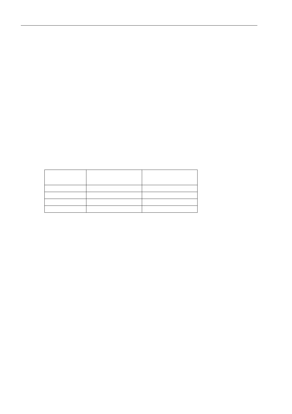
Setting value
Stage df
n
/dt
df/dt HYSTERES.
(Addr. 4519, 4521)
dfx/dt M-WINDOW
(Addr. 4520, 4522)
0.1...0.5 Hz/s ≈ 0.05 25...10
0.5...1 Hz/s ≈ 0.1 10...5
1...5 Hz/s ≈ 0.2 10...5
5...10 Hz/s ≈ 0.5 5...1

 Loading...


