Functions
2.28 90-%-Stator Earth Fault Protection (ANSI 59N, 64G, 67G)
SIPROTEC, 7UM62, Manual
C53000-G1176-C149-7, Release date 03.2010
209
Delay
The stator earth fault trip is delayed by the time set under address 5005 T S/E/F. For the delay time, the
overload capacity of the load equipment must be considered. All set times are additional delay times and do
not include operating times (measurement time, reset time) of the protection function itself.
Earth Current
Addresses 5003 and 5004 are only of importance for machines in busbar connection, where 150 S/E/F
PROT. = directional or non-dir. U0&I0 has been set. The following considerations are not applicable
for unit connection.
The pick-up value 5003 3I0> is set so that for an earth fault in the protected zone, the earth current safely
exceeds the setting.
Since the residual earth current in a resonant-earthed network is very small, also to be independent of network
conditions in general, an earthing transformer with an ohmic loading resistor is normally provided to increase
the residual wattmetric current in the event of an earth fault. Instructions for dimensioning the earth current
transformer and loading resistor are contained in the publication „Planning Machine Protection Systems“, /5/.
Since the magnitude of earth fault current in this case is determined mainly by the loading resistor, a small angle
is set for 5004 DIR. ANGLE, e.g. 15°. If the network capacitances in an isolated network are also to be con-
sidered, then a larger angle (approx. 45°) can be set which corresponds to the superimposition of the capac-
itance network current onto the load current.
The directional angle 5004 DIR. ANGLE indicates the phase displacement between the neutral displacement
voltage and the perpendicular to the directional characteristic, i.e. it is equal to the inclination of the directional
characteristic to the reactive axis.
If, in an isolated network, the capacitances to earth of the network are sufficiently large for earth current cre-
ation, it is also possible to operate without an earthing transformer. In this case an angle of approximately 90°
is set (corresponding to sin ϕ connection).
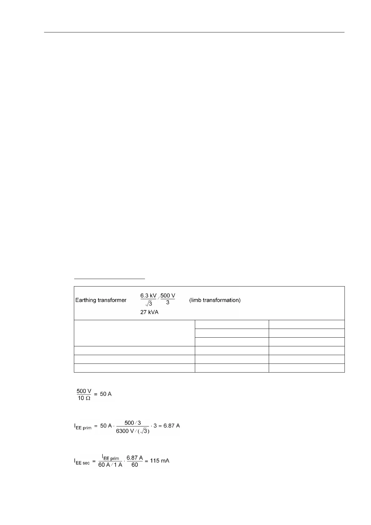
Example busbar connection:
With full neutral displacement voltage, the load resistor supplies
Referred to the 6.3 kV side, this results in
The secondary current of the toroidal transformer supplies to the input of the device
Loading resistance 10 Ω
10 A continuous
50 A for 20s
Voltage divider 500 V / 100 V
Toroidal c.t. 60 A / 1 A
Protected zone 90 %

 Loading...


