Functions
2.31 100-%-Stator Earth Fault Protection with 20 Hz Voltage Injection (ANSI 64G - 100%)
SIPROTEC, 7UM62, Manual
C53000-G1176-C149-7, Release date 03.2010
225
Logic
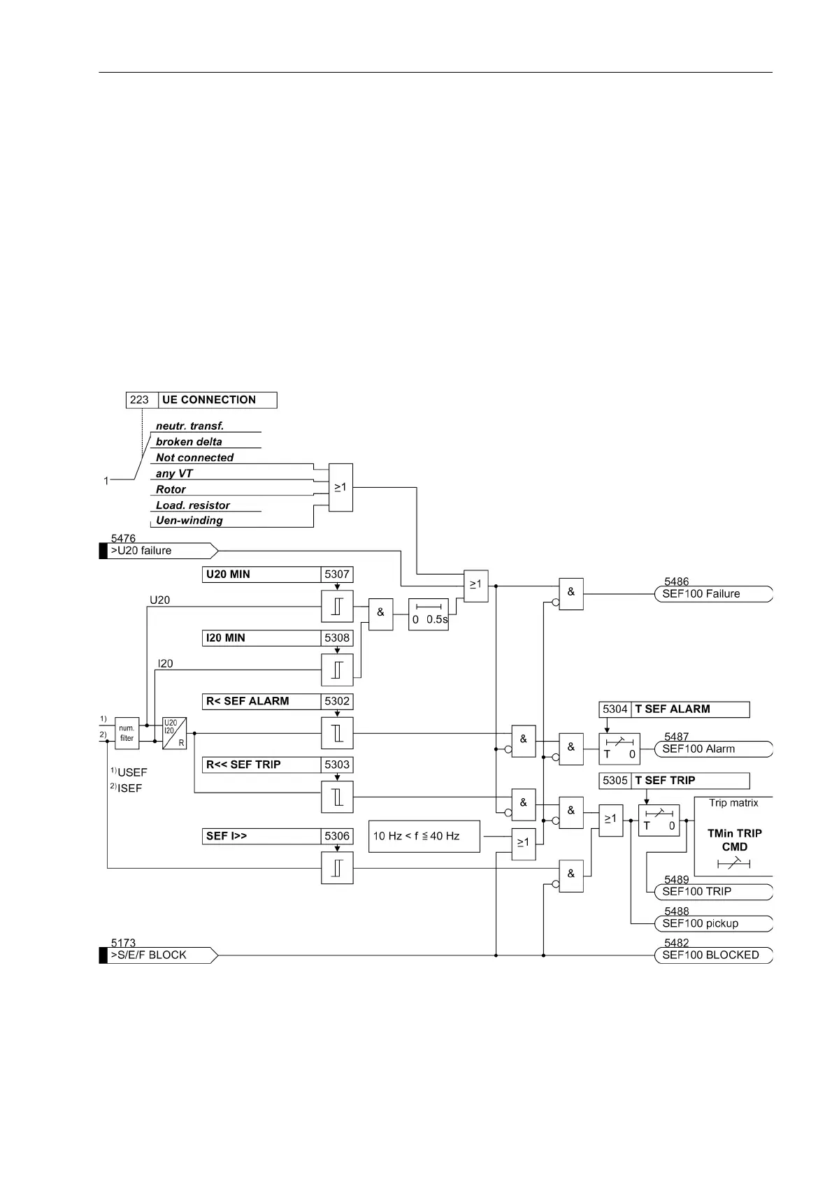
The following figure shows the logic diagram. It comprises:
• Monitoring of the 20 Hz connection
• Resistance calculation and threshold value decision
• Independent current measurement stage
The protection function has an alarm stage and a tripping stage. Both stages can be delayed with a timer. The
earth current detection acts only on the tripping stage. Evaluation of the earth resistance measurement is
blocked between 10 Hz and 40 Hz, because in this frequency range a zero voltage can also be generated by
generators starting up or slowing down. This would then be superimposed on the connected 20 Hz voltage,
causing measurement errors and overfunctioning.
The resistance measurement function is active for frequencies below 10 Hz (i.e. at standstill) and above 40 Hz.
The earth current measurement is active over the entire range.
Figure 2-99 Logic Diagram of the 100 % Stator Earth Fault Protection

 Loading...


