Functions
2.31 100-%-Stator Earth Fault Protection with 20 Hz Voltage Injection (ANSI 64G - 100%)
SIPROTEC, 7UM62, Manual
C53000-G1176-C149-7, Release date 03.2010
229
A two pole isolated voltage transformer must be used with low primary/secondary impedance. This applies
for the 20 Hz frequency.
As the transformation ratio is 1:1, a current transformer with a maximum number of ampere windings must be
chosen.
The CT is installed directly in the starpoint on the earth side, downstream of the load resistor.
Type: 5P10 or 5P15 (or 1FS10)
Rated secondary current: 1 A
Transformation Ratio 1 (1A/1A)
During the primary test the correction angle (address 5309 PHI I SEF) and the ohmic transfer resistance of
the voltage transformer must be determined and set at address 5310 SEF Rps.
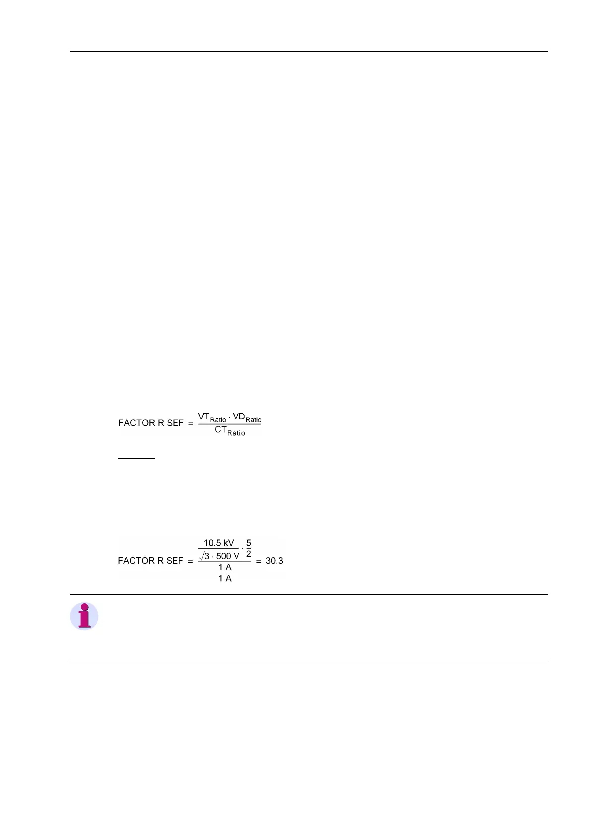
The conversion factor for the resistance (secondary – primary and vice-versa) is:
Example:
Primary Load Resistor: R
L
= 1250 Ω
Voltage transformer: 10.5 kV/ √3/500 V
Ohmic Divider: 1650 Ω/660 Ω (5:2)
Current transformer: 1 A/1 A
Note
Due to the transfer resistance Rps, an ideal transformation ratio of the voltage transformers is not to be expect-
ed. For this reason major deviations of FACTOR R SEF can occur. It is recommended to measure the transfor-
mation ratio with 20 Hz infeed and the machine standing still. This value should then be set.
Primary voltage: U
N,Generator
/ √3
(non-saturated up to U
N,Generator
)
Secondary voltage: 500 V
Power for 20 s
(50 Hz or 60 Hz)
3 kVA
Primary-secondary impedance at 20 Hz Zps < R
L
(but at least < 1000 Ω).
Potential manufacturer: Ritz Messwandlerbau
Salomon-Heine Weg 72
D-20251 Hamburg
(Phone +49 (0) 40511123 333)

 Loading...


