Functions
2.34 Rotor Earth Fault Protection R, fn (ANSI 64R)
SIPROTEC, 7UM62, Manual
C53000-G1176-C149-7, Release date 03.2010
241
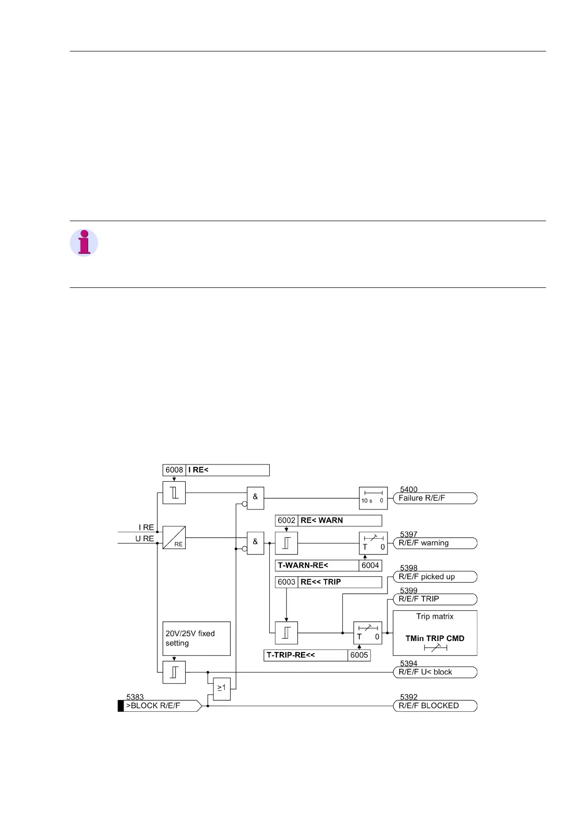
The rotor earth fault protection calculates the complex earth impedance from the auxiliary AC voltage U
RE
and
the current I
RE
. The earth resistance R
E
of the excitation circuit is then calculated from the earth impedance.
The coupling capacitance of the coupling unit C
coup
, the series resistance R
pre
including the brush resistance,
and the earth capacitance of the excitation circuit C
E
are also considered. This method ensures that even rel-
atively high-ohmic earth faults (up to 30 kΩ under ideal conditions) can be detected.
In order to eliminate the influence of harmonics - such as occur in semiconductor excitation equipment (thyris-
tors or rotating rectifiers) - the measured quantities are filtered prior to their evaluation.
The earth resistance supervision has two stages. Usually an alarm is issued if an initial stage (e.g. 5 kΩ to 10
kΩ) is undershot. If the value falls below the second low-resistance stage (e.g. 2 kΩ to 5 kΩ), tripping will be
initiated after a short time delay. The dropout threshold is defined for both stages as 125 % of the set value.
Note
The rotor earth fault protection uses the U
E
voltage input of the device for the detection of the voltage U
RE
. In
this case, the displacement voltage for the 90 % stator earth fault protection U
0
is therefore calculated from the
phase-to-earth voltages.
Supervision of the Measurement Circuit
Since a current flows even during normal operation, i.e. the charging current of the earth capacity C
E
, the pro-
tection can recognize and signal interruptions in the measurement circuit, provided the capacitance to earth is
at least 0.15 µF.
Stabilization of the Resistance Measurement
If the measuring current I
RE
exceeds an internal predetermined value (100 mA), a low-resistance earth fault (R
E
≈ 0) is detected regardless of the calculated resistance. If this current drops below the internal fixed value of
0.3 mA, R
E
→ ∞ is determined regardless of the calculated resistance.
Figure 2-108 Logic Diagram of the Rotor Earth Fault Protection

 Loading...


