Functions
2.35 Sensitive Rotor Earth Fault Protection with 1 to 3 Hz Square Wave Voltage Injection (ANSI 64R - 1 to 3 Hz)
SIPROTEC, 7UM62, Manual
C53000-G1176-C149-7, Release date 03.2010
248
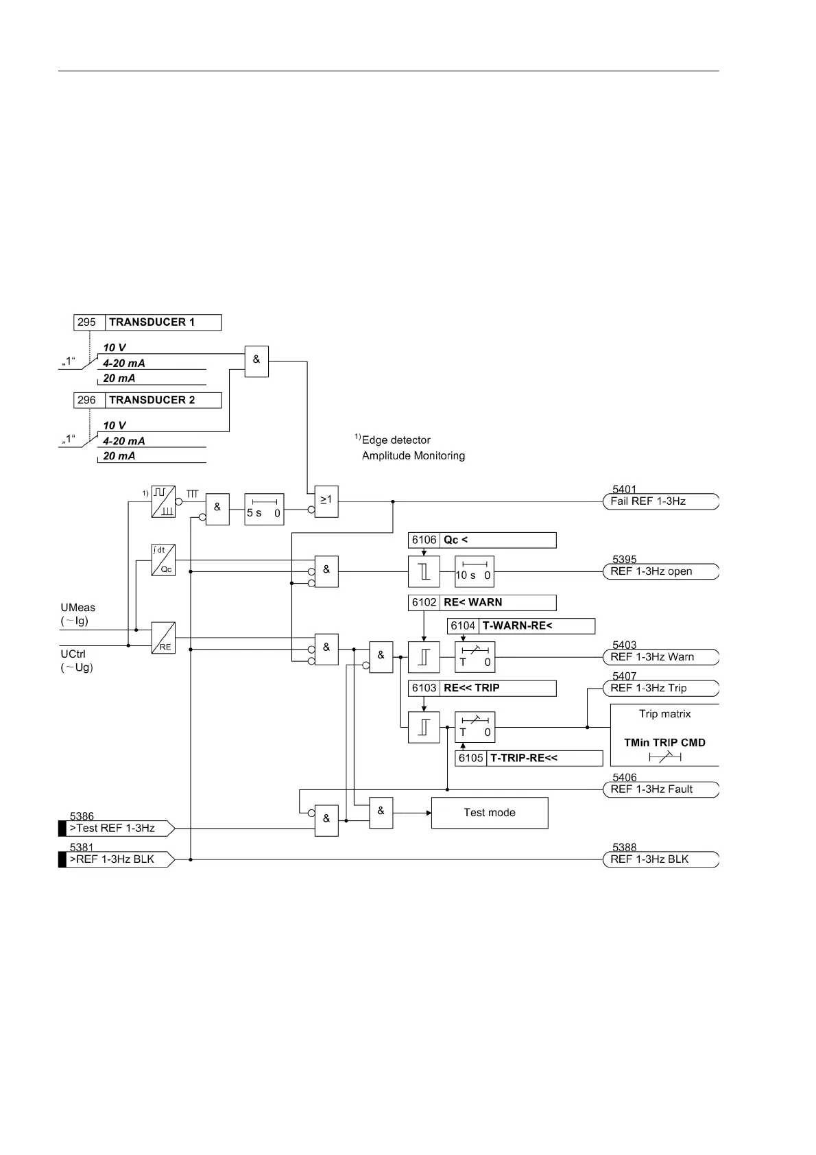
Logic
The logic diagram shows the parts:
• Monitoring of the series device
• Supervision of the measurement circuit
• Two-stage protection function
• Effect of the rotor earth fault protection test
If the earth resistance drops below the high-resistance stage RE<, a warning message will normally be issued.
If it drops below the second, low-resistance stage RE<<, a trip signal is issued after a short time.
Figure 2-113 Logic Diagram of Sensitive Rotor Earth Fault Protection

 Loading...


