Functions
2.42 Monitoring Functions
SIPROTEC, 7UM62, Manual
C53000-G1176-C149-7, Release date 03.2010
283
Measurement Value Acquisition – Currents
In the current paths there are three input transformers each on side 1 and side 2; the digitized sum of the trans-
former currents of one side must be almost zero for generators with isolated starpoint during earth-fault-free
operation. A current circuit fault is detected if
I
F
= | I
L1
+ I
L2
+ I
L3
| > ΣI THRESHOLD S1 · I
N
+ ΣI FACTOR S1 · I
max
or
I
F
= | I
L1
+ I
L2
+ I
L3
| > ΣI THRESHOLD S2 · I
N
+ ΣI FACTOR S2 · I
max
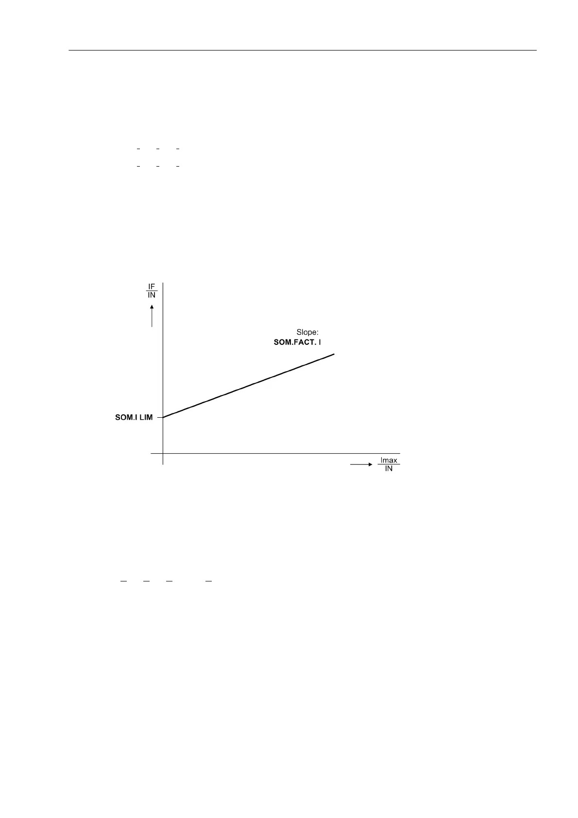
The component ΣI FACTOR S1 · I
max
or ΣI FACTOR S2 · I
max
takes into account admissible current-propor-
tional transformation errors in the input transducers which may occur especially during high fault currents (see
the following figure). The dropout ratio is about 95 %.
This malfunction is reported as „Fail. Σ I Side1“ or „Fail. Σ I Side2“.
The current sum monitoring is only effective for the side for which the starpoint has been configured (address
242 or 244) as Isolated in the power system data.
Figure 2-131 Current sum monitoring
Measured-value Acquisition - Voltages
Four measuring inputs are available in the voltage path: if three of them are used for phase-earth voltages, and
one input for the displacement voltage (e–n voltage from the broken delta winding or neutral transformer) of the
same system, a fault in the phase-earth voltage sum is detected if
| U
L1
+ U
L2
+ U
L3
+ k
U
· U
E
| > SUM.thres. U + SUM.Fact. U x U
max
where SUM.thres. U and SUM.Fact. U are parameter settings, and U
max
is the highest of the phase-earth
voltages. Factor k
U
considers the transformation ratio differences between the displacement voltage input and
the phase voltage inputs (parameter k
U
= Uph / Udelta address 225). The SUM.Fact. U x U
max
component
considers admissible voltage-proportional transformation errors of the input transducers, which can be espe-
cially large in the presence of high voltages (see the following figure).
This malfunction is reported as „Fail Σ U Ph-E“.

 Loading...


