Mounting and Commissioning
3.3 Commissioning
SIPROTEC, 7UM62, Manual
C53000-G1176-C149-7, Release date 03.2010
420
Calibrating the Impedance Protection
Switch impedance protection (address 3301) to IMPEDANCE PROT. = Block relay.
With the primary system voltage-free and earthed, install a three-pole short-circuit bridge which is capable of
carrying rated current (e.g. earthing isolator) to the primary side of the unit transformer.
DANGER!
Primary measurements may only be carried out with the generator at stand–still on disconnected and grounded
equipment of the power system.
Start up machine slowly and excite to 20 % of rated machine current.
Test Instruction
A test with about 20 % of the rated generator current is sufficient for checking the transformer connections and
the operational measured values. If the relative short-circuit voltage of the transformer is small, the voltage
values measured are very low, so that it may be necessary to increase the generator current somewhat. A test
with the full rated generator current is only required for the quantitative calibration of the impedance protection
(e.g. for calibrating the transformer u
SC
).
From the currents and voltages, the protection device calculates the impedance between the point of installa-
tion of the voltage transformer set and the short-circuit position, which is mainly established by the short-circuit
impedance of the unit transformer. Reactance and resistance values can be read out under operational mea-
sured values. For this the protection device automatically considers the rated device current 1 A or 5 A. In the
present case for transformer impedance, the following results:
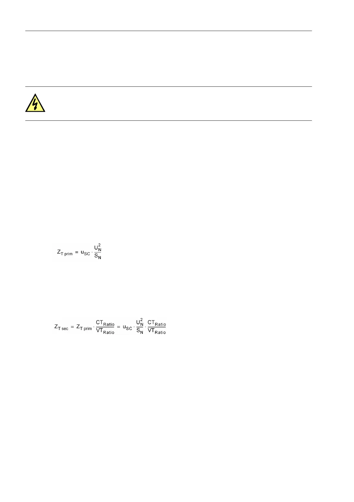
Primary transformer impedance:
with
u
SC
. - relative transformer short-circuit voltage
U
N
. - Rated transformer voltage
S
N
. - Rated transformer power
In secondary values:
with
CT
Ratio
. - Current transformer ratio
VT
Ratio
. - Voltage transformer ratio
If substantial deviations or wrong sign occur, then the voltage transformer connections are incorrect.
After shutdown and de-excitation of the generator, and removal of the short-circuit bridge, the short-circuit tests
are completed. No further tests are required for unbalanced load protection, overcurrent time protec-
tion, thermal overload protection, impedance protection and out-of-step protection.
The time-overcurrent protection and the impedance protection are activated (address 1201: O/C I> = ON or
address 1401 O/C Ip = ON, address 3301: IMPEDANCE PROT. = ON) and work immediately as a short-circuit
protection for all subsequent tests. If used, address 1301 O/C I>> = ON, the thermal overload protection (ad-
dress 1601: Ther. OVER LOAD = ON), the unbalanced load protection (address1701: UNBALANCE LOAD =
ON) and the out-of-step protection (address 3501: OUT-OF-STEP = ON) can be activated. Otherwise, they are
set to Off.

 Loading...


