Mounting and Commissioning
3.3 Commissioning
SIPROTEC, 7UM62, Manual
C53000-G1176-C149-7, Release date 03.2010
427
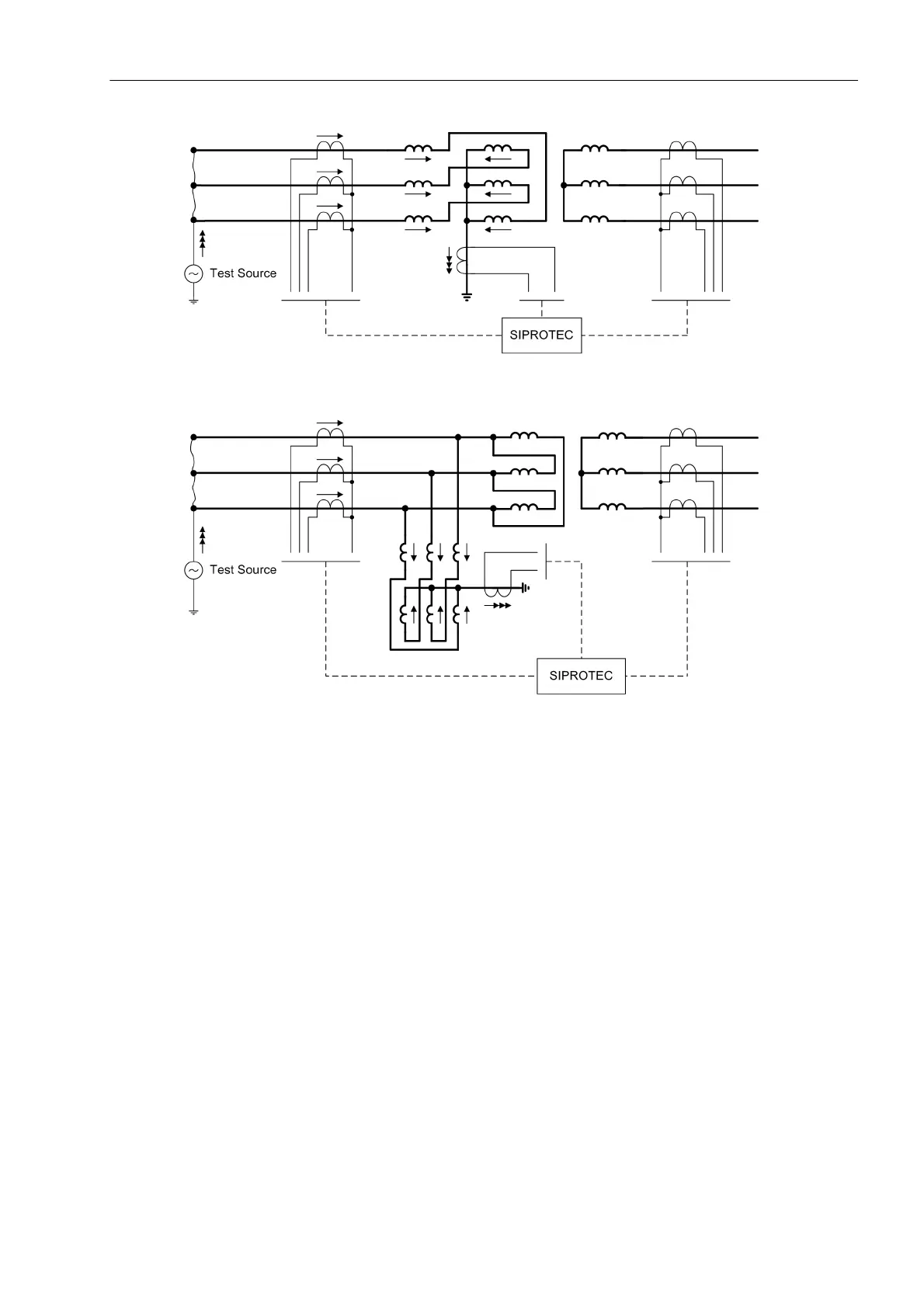
Figure 3-31 Zero sequence current measurement on a zig-zag-winding
Figure 3-32 Zero sequence current measurement on a delta winding with artificial starpoint
A zero sequence current of at least 2 % the rated generator current is required for tests per phase, i.e. the test
current is at least 6 %.
In the protection function, the most sensitive pickup threshold must be set, and the zero voltage release dis-
abled.
• Switch on test current
• Amplitude measurement with switched on test current
In the device at: Measurement → I-Diff, I-Rest) read out the measured values:
3I0-1 calculated zero sequence current of side 1 or side 2 (depending on configuration)
3I0-2 measured earth current I
EE2
I0-Diff calculated differential current
I0-Rest calculated restraint (stabilizing) current
Both zero component currents 3I0-1 and 3I0-2 must be equal and correspond to the injected current. The
differential current I0-Diff is almost zero. The restraint (stabilising) current I0-Stab is twice the flowing cur-
rent. If the differential and the restraint current are equal, the polarity of one CT must be wrong. Minor deviations
are caused by CT errors.
When checking the phase CTs of the allocated side, the measured values correspond (device: Measurement
→ Operational values, secondary) per phase will each be
1
/
3
of the injected zero sequence current. The
phase angle is the same in all 3 phases due to the zero sequence current.

 Loading...


