Mounting and Commissioning
3.3 Commissioning
SIPROTEC, 7UM62, Manual
C53000-G1176-C149-7, Release date 03.2010
431
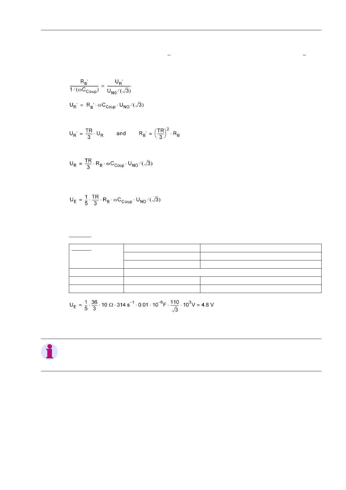
Since the reactance of the coupling capacitance is much larger than the referred resistance of the loading re-
sistor R
B
', U
C
can be assumed to be U
NO
/√3 (compare also vector diagram Figure 3-34), where U
NO
/√3 is the
neutral displacement voltage with a full displacement of the network (upper-voltage) neutral. The following ap-
plies:
With the voltage transformation ratio TR of the earthing transformer:
we obtain:
Together with the voltage divider R
T
(500 V/100 V), this corresponds to a displacement voltage at the input of
the device of:
The pickup value U0> for the neutral displacement voltage should amount to at least twice the value of this
interference voltage.
Example:
10 V has been chosen as the setting value for 5002 in address U0> which corresponds to a protective zone of
90% (see the following Figure).
Note
For use as a neutral transformer the voltage transformation ratio TR instead of TR/3 should be used. As neutral
transformer has only one winding, the result is the same.
Network U
NO
= 110 kV
f
Nom
= 50 Hz
C
coup
= 0.01 µF
Voltage transformer 10 kV / 0.1 kV
Earthing transformer TR = 36
Loading resistance R
B
= 10 Ω

 Loading...


