Mounting and Commissioning
3.3 Commissioning
SIPROTEC, 7UM62, Manual
C53000-G1176-C149-7, Release date 03.2010
444
Caution!
Under-excitation may cause the generator to fall out of step!
Nonobservance of the following procedures can result in minor injury or material damage.
Operation with underexcitation is admissible only for a short period
Proceed as follows:
1. Adjust excitation until the reactive power amounts to approximately Q = 0. To check this, read out the active
power P
0
and the reactive power Q
0
with their respective signs and note them down (see table below).
2. Slowly increase excitation to 30% of rated apparent power of generator (overexcited).
– Read out the motoring power with polarity (negative sign) in the operational measured values and note
it down as P
1
(see table below).
– Read out the reactive power Q
1
with polarity (positive sign) and write it down.
3. Reduce excitation slowly to approximately 30% rated apparent power of generator (underexcited).
– Read out the motoring power P
2
with polarity (negative sign) in the operational measured values under
and write it down (see table below).
– Read out the reactive power Q
2
with polarity (negative sign) in the operational measured values and
write it down (see table below).
4. Adjust generator to no-load excitation and shut it down or select the desired operational state.
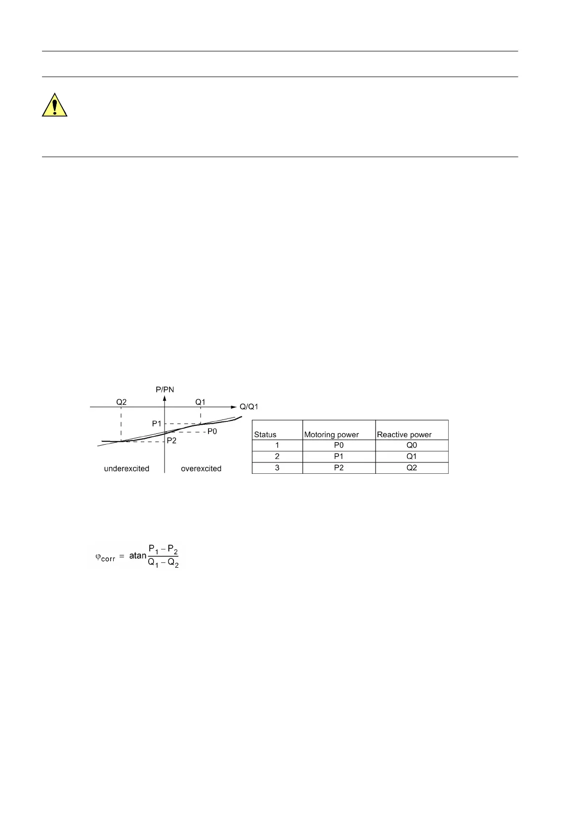
Figure 3-39 Determination of the correction angle W0
The read-out measured values P
1
, and P
2
are now used to carry out CT angle error correction. First calculate
a correction angle from the measured value pairs according to the following formula:
The power values must be inserted with their correct polarity as read out! Otherwise faulty result!
This angle ϕ
corr
is entered with identical sign as the new correction angle under address 204 CT ANGLE W0:
Setting value CT ANGLE W0 = ϕ
corr
A quarter of the sum of the measured values P
1
+ P
2
, also with negative signs, is set as pickup value of the
reverse power protection P> REVERSE under address 3102.

 Loading...


