Functions
2.9 Definite-Time Overcurrent Protection (I>>, ANSI 50, 51, 67) with Direction Detection
SIPROTEC, 7UM62, Manual
C53000-G1176-C149-7, Release date 03.2010
73
Current Trans-former on the Output Side (with direction detection)
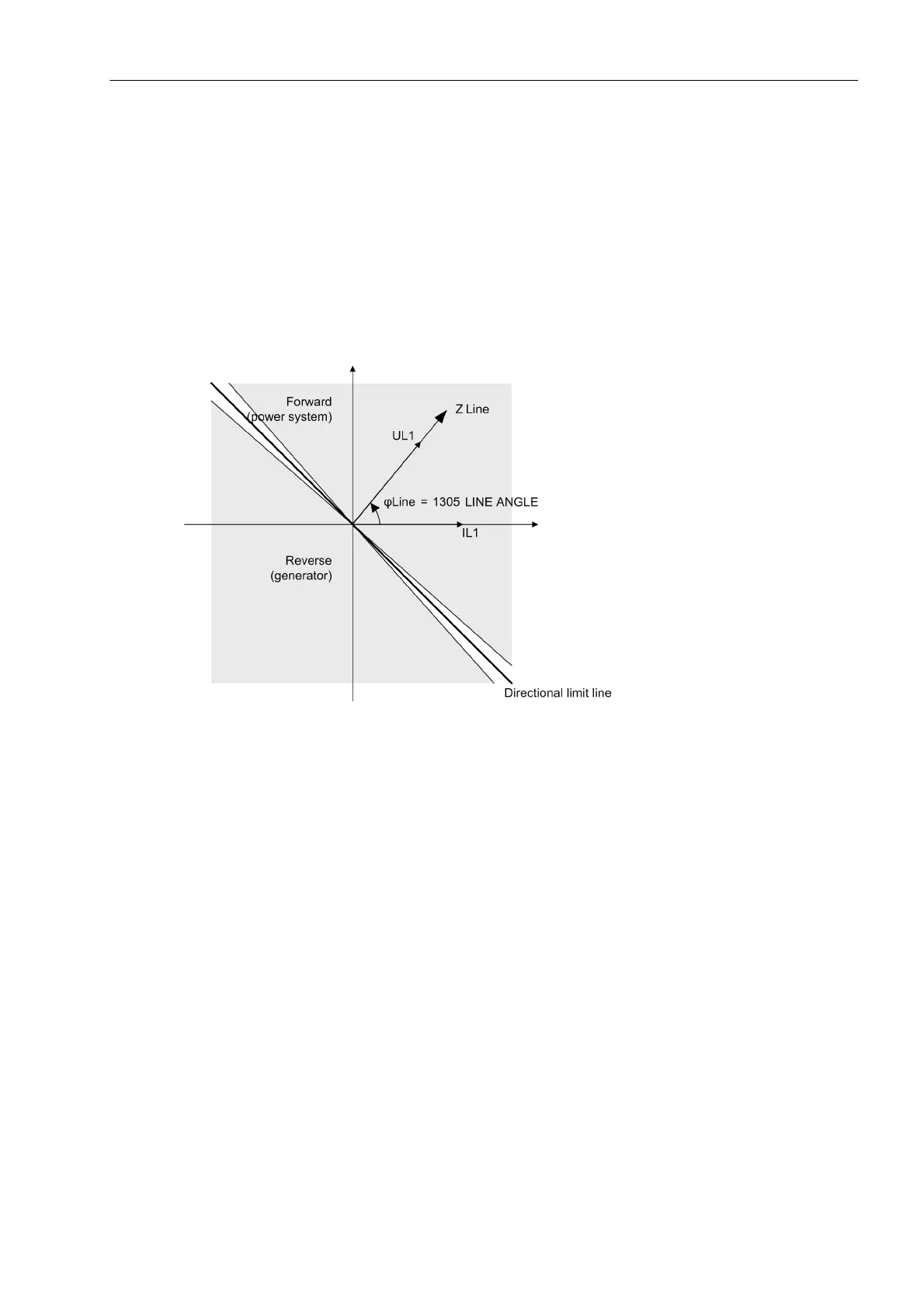
If at address 113 O/C PROT. I>> was configured as directional, the addresses 1304 Phase Direction
and 1305 LINE ANGLE are accessible. The inclination of the direction straight line (see figure 2-16) represent-
ing the separating line between the tripping and the blocking zone can be adapted to the network conditions by
way of the LINE ANGLE parameter. To do this, the line angle of the network is set. The direction straight line
is perpendicular to the set direction angle. Together with the parameter 1304 Phase Direction = Forward
or Reverse, this parameter covers the entire impedance level. This is thereverse direction, provided that the
protective relay has been connected according to Figure 2-13. Between forward and reverse, a small zone is
located in which, due to phase displacement angles of the transformers, a safe direction decision is not possi-
ble. There is no tripping in the configured preferential direction in this zone.
Figure 2-16 Definition of Parameters 1304 Phase Direction and 1305 LINE ANGLE
The setting value of the direction straight line results from the short-circuit angle of the feeding network. As a
rule, it will be more than 60°. The current pickup value results from the short-circuit current calculation. Work-
able pickup values are situated at about (1.5 to 2) · I
N, G
. A tripping time delay of (TI>> ≈ 0.05 s to 0.1 s). is
required to ensure that the effect of the transient phenomena is eliminated.
The corrective value can be determined during machine commissioning (see Section Installation and Commis-
sioning under „Tests with the Network“).
Application Example: Motor Protection
For motors that have no separate current transformers in the starpoint, the following figure shows how to use
the I>> stage as „differential protection“. The configuration of the protection function depends on the transform-
ers. Since this application is most likely to be used for replacements in an existing system, the settings of that
system should be used for orientation.

 Loading...


