104
Configuration Menu
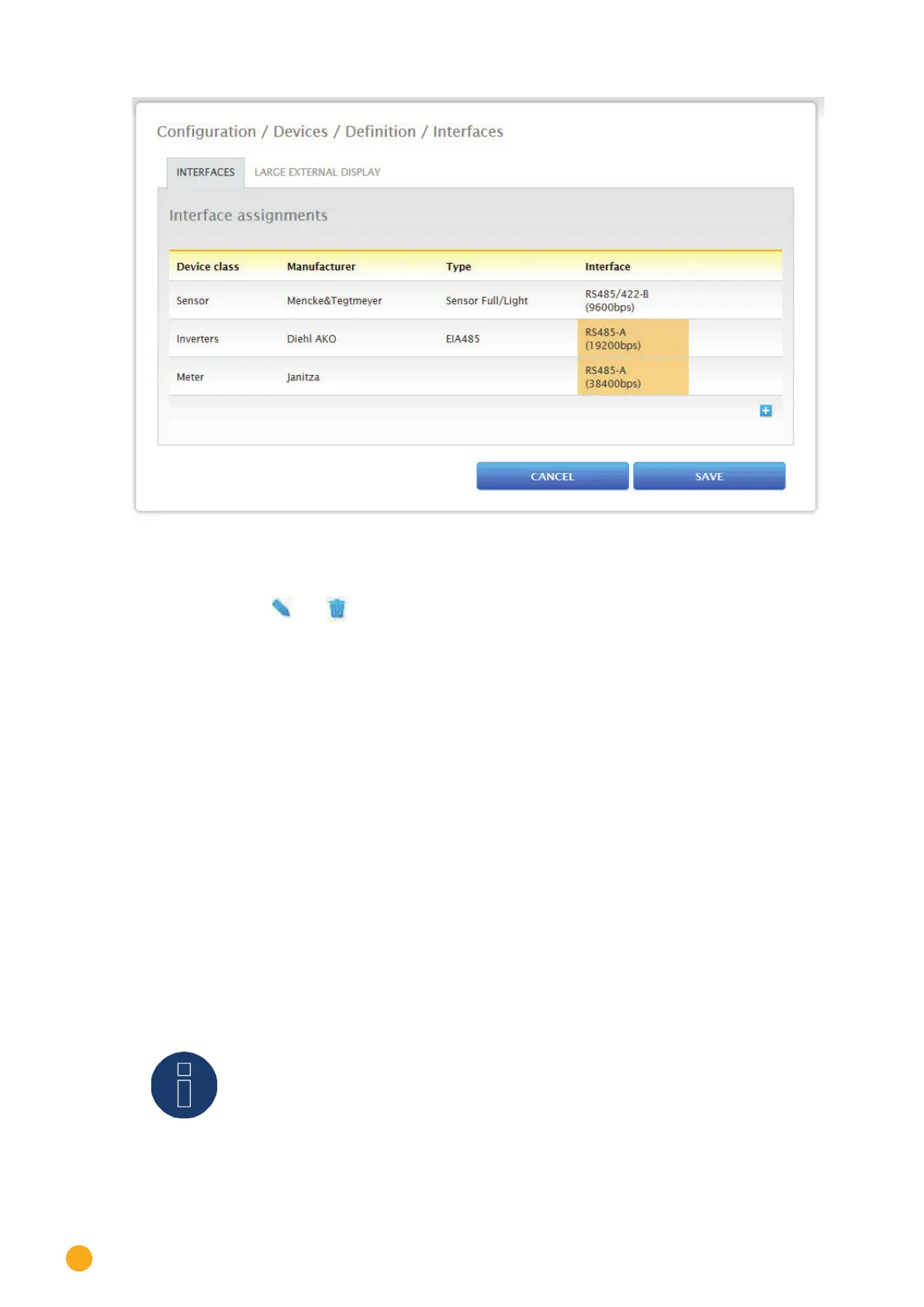
Fig.: Overview of the selected components
From the overview, there is the option to check whether the settings are correct and, if need be, adjust or
delete them with the
and symbols. (The symbols are only displayed by moving the mouse over the
components.) Additionally, the following is displayed in the overview of the device interfaces:
•
Device class
The selected devices can be seen here. In the example:
• Sensor
• Inverter
• Meter
•
Manufacturer
The manufacturer is displayed in this column. In the example:
• Mencke&Tegtmeyer
• Diehl AKO
• Janitza
•
Type
The defined types are listed in this column. In the example:
• Sensor Full/Light
• EIA485
•
Interface
Interface indicates which interface and baud rate the devices are using.
Click on SAVE if all of the definitions are correct.
Note!
The number behind the interface (e.g. x1) indicates the number of switching devices for
this device type.